Today I finished some of the Beomaster 1900 service manual adjustments and began looking at its performance with THD (total harmonic distortion) and Frequency Response.
First a couple of service manual adjustments to make.
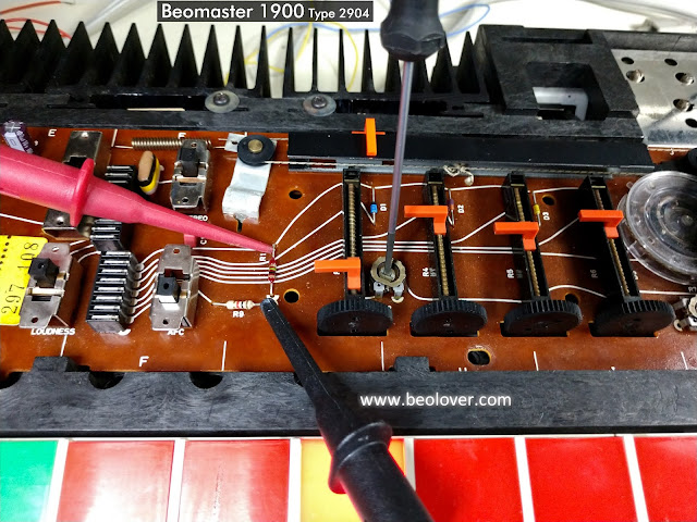
The Beomaster 1900 service manual calls for adjusting the tuning voltage for FM 1 and FM 5.
Specifically, the FM 1 tuning potentiometer (4R3) is to be set on the 88MHz dial position.
With FM 1 selected as the Beomaster 1900 music source the 4R2 trimmer is adjusted so test point 4TP1 measures 4.5 VDC.
Similarily, the FM 5 tuning potentiometer (4R7) is set to 88MHz. With FM 5 as the selected music source trimmer 4R8 is adjusted to get 4.6 VDC ... also at test point 4TP1.
Here are those measurement and adjustment points.
The last service manual adjustment I made was to adjust the output level trimmer 2R136.
For this adjustment an input signal of 200mVrms, 1KHz (sine wave) is applied to the Beomaster 1900 Tape input. With the Beomaster 1900 volume preset on the middle setting the Beomaster is turned on by selecting the Tape source button. At that volume level the output of the Beomaster (as measured at the speaker outputs) should be at 100mV. Trimmer 2R136 is used to adjust that level.
I set the test up by configuring a 200mVrms, 1KHz test signal out of the QuantAsylum QA401 Audio Analyzer. I verified the signal with an oscilloscope then applied it to the Beomaster 1900 tape inputs.
I set the volume preset to the middle button and selected the Tape source button to turn the Beomaster 1900 on. Then I measured the voltage at speaker loads.
Here is the test setup and the measurement results.
The left and right channels differ in output by 20mVrms. That isn't horrible but I expect them to be closer.
The Balance control was correctly in the center. The no-load current adjustments are almost identical.
I guessed that the problem must be in the Beomaster 1900 volume control LDR device.
That is a light controlled resistor device that uses a lamp whose intensity changes via electronic control. The amount of light then changes the resistance values of a set of photo resistors to control the Beomaster 1900 volume levels.
Just to investigate a little further I went ahead and checked the Beomaster 1900 THD (total harmonic distortion) at 30Watts (with 8 ohm dummy speaker loads).
The THD values are good but the left channel is at about 20 Watts while the right channel is at about 30 Watts.
I needed to investigate the volume control LDR device.
Here are some photos of it.
The photo shows four LDR devices around the lamp in the volume control device.
Two LDR devices are for the left channel and two are for the right channel.
One set (L & R) are for voltage levels in the tone control circuit and the other set (L & R) are for the voltage level in the output amplifier.
To test this device out I connected the two wires for the lamp to a DC power supply and set the voltage to 5 VDC. Then I measured the resistance of each of the four resistors to see how close in value they were to each other.
I discovered that the four LDR devices in the volume control of this Beomaster 1900 unit did not have a consistent resistance value for my test voltage.
I measured several LDR devices with my test setup and selected four LDR devices that were very close to each other in value.
I reinstalled those into the volume control casing and then back into the Beomaster 1900.
Then I repeated the Tape input level adjustment.
This time the difference in the left and right channel is about 7mVrms. That is much better than the previous 20mVrms difference.
What about the left and right channels at maximum power output?
The Beomaster 1900 spec sheet says the maximum power output of the Beomaster 1900 amplifier is rated at 2 x 20 W/8 ohms. The maximum total harmonic distortion is listed as less than 0.2%.
Due to the nature of the touch sensitive volume control it is difficult to dial in a precise volume level for this check. I ended up with measurements at output levels of 15W, 28W and 32W.
All three measured well below the target 0.2% THD value.
Here is the THD measurement at 28 Watts across my dummy 8.1 Ohm speaker loads.
Also notice that the left and right channel output levels are much closer to each other than before I worked on the volume control LDR device. I am satisfied with these results.
The last test is a frequency response test. I set the voltage level to output 26W of output from the Beomaster 1900 amplifier across the 8.1Ohm dummy speaker loads.
Here are the measurements from my QA401 Audio Analyzer.
I will continue on with the reassembly of the Beomaster cabinet parts then put the unit into listening testing.
While I am doing that I will begin a couple of fun Beogram turntable restorations and a change of belts on a Beogram CD50 unit.


No comments:
Post a Comment
Comments and suggestions are welcome!