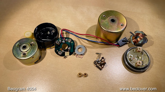
I recently received the DC platter motor, the main PCB and the RPM panel from a Beogram 4004 located in Virginia for restoration. As usual I started with the platter motor since the oil infusion of its bearings can take several days. This shows the motor:
I disassembled it to get the bearings out:
The bearings are the two small donuts up front. I immersed them in motor oil and pulled a vacuum. Immediately, strong bubbling started as the vacuum drew the air from the porous bearing material, making room for oil to diffuse into the bearing:
After ~3 days the bubbling finally stopped and I extracted the bearings:
I reassembled the motor for testing with the rebuilt PCB and RPM panel.
This shows the restoration of the main PCB. In original condition:
This is the original RPM section composed of single turn RPM trimmers and a National brand relay that switches between 33 and 45 RPM:
This is a close-up of the sensor arm signal amplifier, which is responsible for detecting the presence of a record on the platter:
I replaced all electrolytic capacitors with modern 105C rated units and replaced the RPM circuit components with modern multi-turn trimmers and an encapsulated relay on an adapter board that fits the National relay pinout:
This shows the restored RPM section:
Then it was time to replace the incandescent light bulbs in the RPM panel. This shows the panel:
Removal of the bulb covers reveals the bulbs:
I replaced the bulbs with LEDs on small adapter boards that can be soldered inplace of the original bulbs:
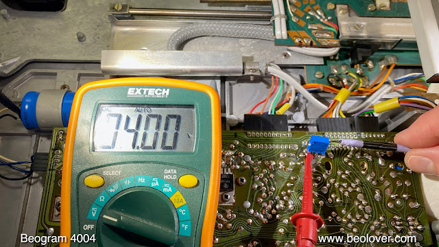
Then it was time to test everything in one of my Beograms. First I adjusted the sensor arm amplifier bias:
Then I moved the bias trimmer to the component side next to the new high-gain transistor that I installed (in many cases these transistors lost some of their gain at this point in time, which can disable the record detection circuit, i.e. it is a good idea to replace them with modern units):
Then I measured the sensor signal:
This is a very good result. Per service manual the amplitude should be 5V+. Each dip represents one of the black ribs on the platter as they pass underneath the sensor arm. The next step was measuring the RPM stability of the restored motor. This shows the BeoloverRPM device in action, which can log the RPM for extended periods of time:
This is the RPM curve that I measured over 24 hrs:
This curve is pretty good, but there are some small deviations (that are much too small to be audible). This slight choppiness happens sometimes and usually goes away after using the Beogram for a while. This means these parts are ready for action again and I will soon send them back to Virginia.


No comments:
Post a Comment
Comments and suggestions are welcome!