In the last post I removed the Beogram 4004 floating chassis and tangential arm assembly to clean, lubricate and check the various components involved. This post dives in to the actual work tasks.
With the Beogram floating chassis and tangential arm assembly removed I can easily inspect and get to various components that I was planning on either restoring, replacing or adjusting.
I removed the arm lowering damper in the previous post so a good place to start is to clean off the old oil/grease and lubricate with new oil.
The old oil seemed a little thick and the damper did not operate smoothly.
Here are the damper parts cleaned and ready for reassembly.
The new oil I am using for this component is some PMX-200 clear silicone fluid.
Here is the assembly lubricated and reassembled.
Before reinstalling it in the tangential arm assembly however, there are still other things to do and leaving the damper out for now gives me more room.
One thing I like to do when I have the tangential arm assembly out by itself is to work the mechanical parts by hand and get a feel if everything is operating smoothly.
On this Beogram's arm assembly most of it looks and works good. There was that problem with the damper that is now fixed. The lever for lowering and raising the arm moves easily. The solenoid however felt a little off. When pushing the metal press-bar and armature manually I noticed it would always stick the first time. After that is worked nicely. But after sitting for a while it would stick again.
I decided to remove the solenoid and investigate further.
With the solenoid all by itself I operated it manually every so often, then leave it for a while and try again. I kept observing the same thing. An initial sticking of the press-bar before sliding in and out.
Here is the unloaded solenoid from the Beogram 4002 Type 5513 unit.
This second solenoid engages the press-bar and armature at only about 300mA and just about 3 VDC.
The second solenoid also always easily operates manually when I push the press-bar in and out. It never sticks.
I feel more comfortable going forward on this project with the second solenoid so I am going to replace the original with the one from the Beogram 4002.
Another component on the tangential arm assembly I worked on while the solenoid and damper were removed is the tracking sensor. I could see a little excess oil below the tracking sensor housing. There really shouldn't be any there. I have seen that happen before though. It is a result of over oiling the Beogram. Extra oil ends up running to the bottom of the assembly and collecting in the lowest spots.
Here you can see the oil on the underside of the tracking sensor.
Here are the components dried off and ready to use.
I continued with the restoration work on the tracking sensor assembly while was here.
This Beogram 4004 restoration is going to replace the original tracking sensor light source with the Beolover LED tracking sensor assembly. I did some adjustment of the tracking sensor mechanical parts while things are apart. This is the time to check that the moving parts are at a good starting point before the tracking sensor adjustment procedure later in the project (during the service manual checks).
I made sure that the tracking sensor assembly diaphragm is about 1mm above the sensor housing. It needs to be close but it must also be able to comfortably move without obstruction.
I try to center the diaphragm with the tracker sensor housing as well while everything is easy to reach.
I also center the eccentric screw used to adjust the tracking during the adjustment procedure.
You can see in the photo below that the eccentric screw can only adjust the tracking sensor housing a total of about 3 or 4 mm. I want to start with the adjustment screw in its center position before I get to the adjustment procedure later.
The top piece of the tracking sensor assembly is of course the Beolover LED assembly.
The diaphragm securing screw and the eccentric adjustment screw will provide the coarse adjustments during the service manual adjustment procedure. The little trimmer on the top of the Beolover assembly provides the fine adjustments (by varying the intensity of the LED).
That is all I can do on the tracking sensor assembly for now. I will return to it when the Beogram is reassembled and I am doing the service manual checks.
Another sensor I went ahead and replaced while the tangential arm assembly was handy is the fixed arm record detection sensor's light source. This is another lamp that the owner would like the Beolover replacement assembly for. It is pretty easy to replace. You just have to be a little careful with a couple of very thin and delicate wires.
Like the tracking sensor the final adjustment of this sensor will be performed at the end when I am going through service manual adjustments. The resulting record detection signal will be checked on an oscilloscope and the 2MΩ trimmer I added to PCB 1 for this circuit will be used to adjust the signal.
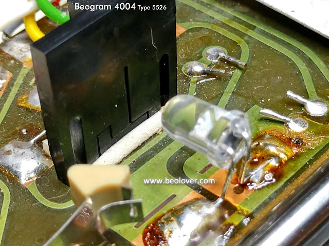
There is one more sensor lamp to replace while the Beogram is openend up. That is the 4D1 LED that makes up the Beogram 4004 position sensor. That is the sensor that reacts to the black bars on the acrylic scale that passes between the sensor and the light source as the tangential arm assembly moves forward. I replace that with an amber LED.
That is all there is to do on the position sensor for now. There is a trimmer for its signal on PCB 1 and I will measure and adjust that during the service manual checks.
Looking at the servo motor again on this floating chassis assembly I felt like I couldn't leave it with its original damping material. I opened the motor housing again and pulled off the old damping material. I was glad I did. It just fell apart without any effort. It would have still worked for a while but it was destined to fall apart into tiny pieces in the future. Better to deal with it now.
The replacement material I use is a neoprene padding used in RC motor vehicles. It will do a great job.
I installed the new aluminum pulley for the tangential drive spindle when I reinstalled the servo motor with its new damping material in place.
Before I move to the lubricating step I wanted to do a preliminary adjustment on the Beogram 4004 tonearm tracking force. It is another task that is easy to do while the tonearm assembly is removed.
I like to set the tracking force dial to the 1 gram position then adjust the counter-weight on the back of the tonearm so that it is calibrated to be 1 gram as measured with my digital scale.
Starting with the floating chassis I mix together some Esso Nuto H32 oil with some Rocol MTS 2000 grease. The service manual says the mixture should be an oily consistency so not a thick paste but also not too thin.
The service manual also specifies Rocol MTS 1000 grease but I could only get small tubes of MTS 2000. I asked the Rocol technical department what the difference was between MTS 1000 and 2000. Their answer was that the two were pretty much the same except the MTS 2000 grease is a little thinner.
I will mention again that substituting modern synthetic oil and grease is fine. I would not use anything really thick on the spindle though. You don't want to use too thin an oil either though. When the Beogram is fast scanning the spindle turns quite fast. Thin oil will get thrown all over the inside of the Beogram. The reason I try to find and use the products specified in the service manuals is simply a personal preference. :-).
Moving back to the tangential arm assembly...Here are the lubrication points the service manual calls out.
The service manual calls for Castrol Everyman Oil for the arm oil points and Valvata 79 Oil for the magnet coil spring damping material. Those are two products I don't have and can't find so I use a thin, synthetic oil substitute for those points. Remember not to use too much. There should not be excess oil dripping down from the oil points.
The photo above of course shows the tangential arm components all nicely in place again.
The only tricky component to remove and reinstall is Arm 193. It has a locking ring on the pivot point.
I use pliers designed just for those type of lock rings to remove and install them.
Now to reinstall the tangential arm assembly back on the floating chassis assembly.
The drive spindle must be fit onto the arm assembly as the arm assembly is fit onto the two tie-rod shafts.
The two tie-rod shafts (82 and 137) are to be coated with some Molykote DX (white) paste. The service manual says to coat the entire surface of the tie-rod shaft. It also says to use some of the paste on the spindle bearing where it fixes to the chassis. Where it rotates.
Here are the tangential arm and floating chassis assemblies fit together again.
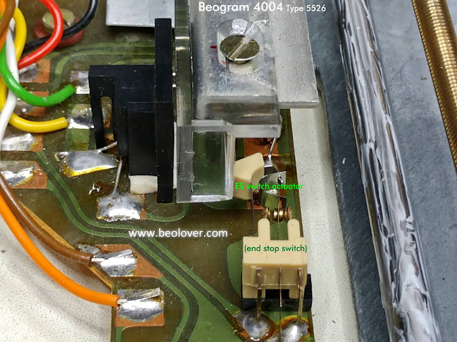
I reinstalled the acrylic position scale on the tangential arm assembly last and aligned it so it could operate the SO (shut off) and ES (end stop) switch actuators correctly.
That alignment of the position scale will be checked again during operational testing of the Beogram later.
I will do those tasks as well as lubricate the main bearing on the next post.


No comments:
Post a Comment
Comments and suggestions are welcome!