Featured Post

Beolover SyncDrive: DC Platter Motor Replacement for Beogram 4002 and 4004 (Type 551x and 552x)

Late Beogram 4002 and the 4004 (Types 551x and 552x), which have DC platter motors instead of the earlier synchronous AC motors usually suff...

Showing posts with label power supply checks. Show all posts

Monday, June 5, 2023

Beogram 8000 Type 5513: Tomball Texas Project Final Adjustments and First Record Play

The Beogram 8000 restoration project from Tomball, Texas is playing records again.

To get to this point I had to perform some remaining adjustments.

First was the forward/reverse scanning LDR adjustments.  Those are for the tonearm forward and reverse buttons on the control panel.  The Beogram 8000 uses a couple of LDR devices (resistors that change value when light hits them) and a rocker spring that is an aperture for the light source to strike the LDR.
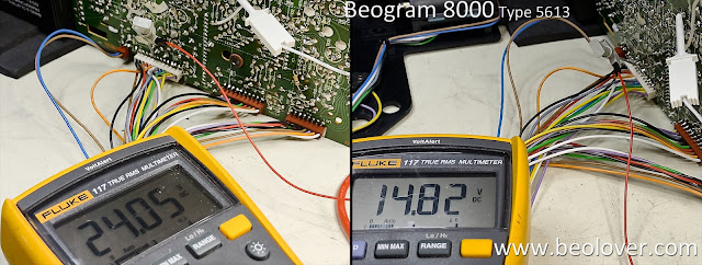
The steady state voltage level of the two LDR devices (forward and reverse) should be around 620 millivolts (DC). I like to set them at around 650 mVdc. They are dialed in by an adjustment screw that affects the amount of light to the sensor.  

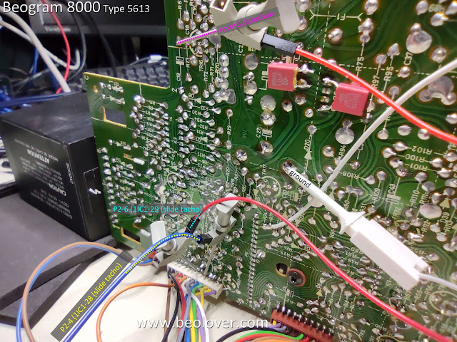
The adjustment screws are a rather coarse adjustment and is why I installed the little test connector to make tweaking the setting easier (especially after the Beogram 8000 is fully reassembled in its cabinet).

Here are the forward and reverse, steady-state measurements for the LDR devices.


I also measured the +5 VDC, +15 VDC and -15 VDC power supplies again.
I measured the +5 VDC at the filter capacitor inside the PCB 2 assembly that supplies power to the microcomputer (uC).


I checked the +15 VDC voltage going into the regulator and coming out of the regulator.


I measured the -15 VDC off the 1TR19 collector where that voltage regulation output is located.


From there I moved to making some measurements on the oscilloscope of the speed sensor, the two position sensors and the record detection sensor.

For the speed sensor I measured the raw signal coming off the sensor assembly, then at uC (2UI1-40) after the signal has been filtered.

Here is the measurement point for the raw signal from the sensor assembly (P4 pin 7).


Here is the measurement point on 2IC1-40 (uC).


...and here is what the oscilloscope shows.


Next are the measurements for the two position sensor signals and the record detector signal.
I made those measurements with the tangential arm assembly moving forward and in reverse.

Here are the measurement points.


...and the oscilloscope measurements.


The supply voltages and sensors all looked good so I moved to the final two adjustments on this Beogram 8000.

The first adjustment was to check the phono cartridge tracking force and adjust it if necessary.
The second adjustment was to set the sensitivity of the tangential tracking sensor.

For both of these adjustments I need the Beogram 8000 where I can operate it but I don't want the platter to rotate.  With a belt driven turntable it is just a matter of removing the belt.
On the Beogram 8000 it means disconnecting the P4 connector on PCB 1.  

Just to be safe, disconnect and connect the cables with the Beogram unplugged from the wall.


The tracking force and tracking sensitivity are both adjusted on the tonearm assembly.


The tracking force for the phono cartridge is always available for the owner to set using the small adjustment slider under the tracking force scale (along the side of the tonearm).
What I do during the service manual checks is calibrate the tracking weight so it is as close to 1 gram as I can get it with the slider set to "1" on the scale.

To do that I use a digital scale and adjust the tracking force counter-weight position as necessary to get 1 gram on the measurement.

Note: I make the tracking force measurement with the platter turned upside-down because it is flat enough for the measurement scale to rest on.


On the tracking sensitivity adjustment the procedure is to place a test record on the platter, then advance the tonearm over a test track (usually in the middle of the record) and set the arm down.
I also set the arm down (with a phono cartridge attached) before that and make sure that the tracking sensitivity isn't too sensitive where the arm starts moving forward by itself.

The arm should lower straight down and the phono stylus sits in the record groove with no forward advancement of the servo motor (that drives the tonearm assembly).

Next, the platter is manually rotated and the servo motor is observed for movement.
The servo motor should advance the arm within one or two revolutions of the platter to begin with, then every platter revolution after.

Should the tracking sensitivity require adjustment, there is a small adjustment screw on the side of the tangential arm assembly...shown here.


That completes the Beogram 8000 adjustments.  Now it was time to actually play a record.

I will do more complete record play testing later, when the Beogram 8000 is fully assembled.
At this point however, I like testing record play with my Workshop Beomaster 8000.
Besides being anxious to listen to a record, now is a good time to check the record play functions.
If there was a problem, the Beogram 8000 is already open for trouble-shooting.

I like testing with a Beomaster 8000 because the two components are integrated with their controls.
Pressing Play on the Beogram 8000 will cause the Beomaster 8000 to turn on and switch to the phono (PH) source.  Pressing PH on the Beomaster 8000 will cause the Beogram 8000 to start playing a record.

Note: I keep my Workshop Beomaster 8000 opened up for servicing at all times so I can use it for Beomaster 8000 board testing. Just like I keep my Workshop Beogram 8000 opened up.

The first record play test performed perfectly so I just relaxed and finished the day listening to some vinyl.












Wednesday, January 25, 2023

Beogram 8002 Type 5633: Initial Power Checks

The Beogram 8002 turntable allows you to connect together the floating chassis with the electronic control boards outside of the cabinet. That makes it easier to test and very convenient.

I used that capability to check out my completed restoration tasks so far.
I wanted to see what works and what doesn't work on this turntable after my initial work.

The first thing to check is the power supply so I assembled the parts and plugged the transformer in to the wall.

Most of the time on this type of restoration I immediately get the little, red Standby dot on the display when I plug in the Beogram for the first time.
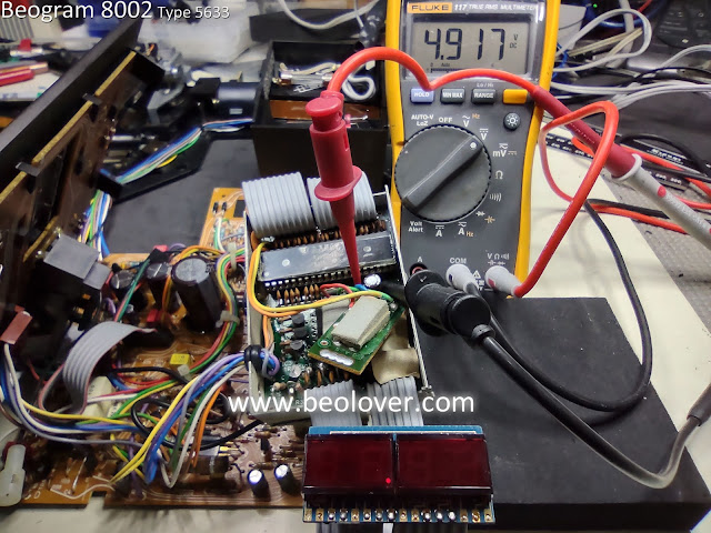
In this case, it was blank...but as you can see in the photo, I was measuring the +5V regulator and it does show a proper voltage. 
So this was some connection problem.


Checking the other Beogram 8002 supply voltages I found that everything had power.

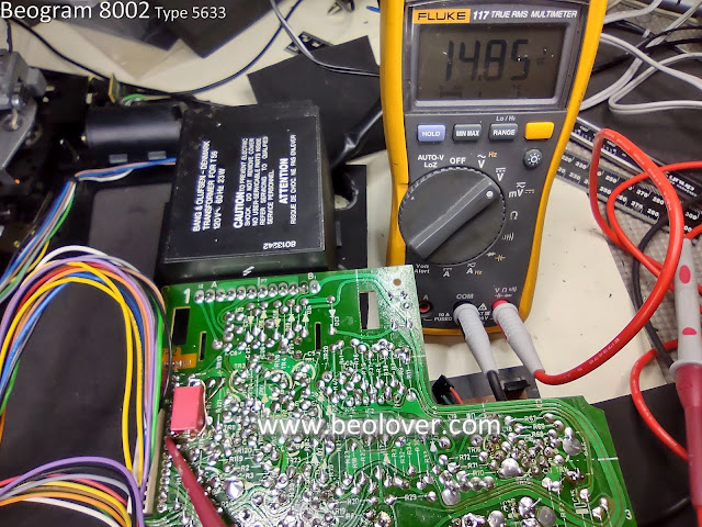
Here is the +24V across the 1C27 filter capacitor.


Here is the -24V across the 1C29 filter capacitor.


The 1C24 capacitor measured around 13V that goes to the +5V regulator.


...and the regulated +5V signal to PCB 1 is good.


The problem was that the +5V power was not reaching the 2C28 capacitor on PCB 2.
That wasn't too surprising as connection problems do occur with these turntables.
One item I have never been fond of with the Beogram 8002 (and 8000) design is the PCB 1 P6 connector and ribbon cable to PCB 2.  

It is a press-to-fit connector and often times the ribbon cable does not feel like it mates securely enough.
That was the case here.

Re-seating the cable a couple of times allowed me to finally get the Beogram 8002 to come on in the Standby mode.


I didn't want to leave it like this though.
It would be too easy for the cable to lose a connection again.

I decided to cut away more material from the channel areas of the ribbon cable so I could seat the cable further into the P6 connector.


That worked much better and the cables don't just fall out of the connector like they did before.


Now that the Microcomputer board has proper power I can turn the Beogram 8002 on and check the ±15V regulated supplies.

They both look good.


Moving on, I checked the platter drive and observed that the 33.33 and 45 RPM speeds worked.


I also tested the arm lowering and the solenoid control mechanism appears to work great.


That was just a quick set of tests to see if there are any major problems with the restoration so far.

There doesn't appear to be so I will move on to checking the various sensor signals on the Beogram 8002 and make sure they are working properly.

Saturday, March 20, 2021

A Pair of Beomaster 1900 Receivers for Restoration: Unit #2 Performance Testing and a Volume Control LDR Problem

Today I finished some of the Beomaster 1900 service manual adjustments and began looking at its performance with THD (total harmonic distortion) and Frequency Response.

First a couple of service manual adjustments to make.
The Beomaster 1900 service manual calls for adjusting the tuning voltage for FM 1 and FM 5.
Specifically, the FM 1 tuning potentiometer (4R3) is to be set on the 88MHz dial position. 
With FM 1 selected as the Beomaster 1900 music source the 4R2 trimmer is adjusted so test point 4TP1 measures 4.5 VDC. 

Similarily, the FM 5 tuning potentiometer (4R7) is set to 88MHz.  With FM 5 as the selected music source trimmer 4R8 is adjusted to get 4.6 VDC ... also at test point 4TP1.

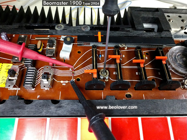
Here are those measurement and adjustment points.


The last service manual adjustment I made was to adjust the output level trimmer 2R136.
For this adjustment an input signal of 200mVrms, 1KHz (sine wave) is applied to the Beomaster 1900 Tape input. With the Beomaster 1900 volume preset on the middle setting the Beomaster is turned on by selecting the Tape source button. At that volume level the output of the Beomaster (as measured at the speaker outputs) should be at 100mV.  Trimmer 2R136 is used to adjust that level.

I set the test up by configuring a 200mVrms, 1KHz test signal out of the QuantAsylum QA401 Audio Analyzer.  I verified the signal with an oscilloscope then applied it to the Beomaster 1900 tape inputs.
I set the volume preset to the middle button and selected the Tape source button to turn the Beomaster 1900 on.  Then I measured the voltage at speaker loads.

Here is the test setup and the measurement results.


The left and right channels differ in output by 20mVrms. That isn't horrible but I expect them to be closer.

The Balance control was correctly in the center. The no-load current adjustments are almost identical.
I guessed that the problem must be in the Beomaster 1900 volume control LDR device.
That is a light controlled resistor device that uses a lamp whose intensity changes via electronic control. The amount of light then changes the resistance values of a set of photo resistors to control the Beomaster 1900 volume levels.

Just to investigate a little further I went ahead and checked the Beomaster 1900 THD (total harmonic distortion) at 30Watts (with 8 ohm dummy speaker loads). 


The THD values are good but the left channel is at about 20 Watts while the right channel is at about 30 Watts.

I needed to investigate the volume control LDR device.

Here are some photos of it.


Here is a photo of the volume control LDR device disassembled.
A single lamp in the center of the device emits light to four LDR devices.
When there is no light the resistance level of the LDR is at its highest and corresponds to full volume of the Beomaster 1900 amplifier.
As the lamp begins to emit light the LDR resistance decreases and attenuates the audio signal.


The photo shows four LDR devices around the lamp in the volume control device.
Two LDR devices are for the left channel and two are for the right channel.
One set (L & R) are for voltage levels in the tone control circuit and the other set (L & R) are for the voltage level in the output amplifier.

To test this device out I connected the two wires for the lamp to a DC power supply and set the voltage to 5 VDC.  Then I measured the resistance of each of the four resistors to see how close in value they were to each other. 

I discovered that the four LDR devices in the volume control of this Beomaster 1900 unit did not have a consistent resistance value for my test voltage.

I measured several LDR devices with my test setup and selected four LDR devices that were very close to each other in value. 

I reinstalled those into the volume control casing and then back into the Beomaster 1900.
Then I repeated the Tape input level adjustment.

This time the difference in the left and right channel is about 7mVrms.  That is much better than the previous 20mVrms difference.


What about the left and right channels at maximum power output?

The Beomaster 1900 spec sheet says the maximum power output of the Beomaster 1900 amplifier is rated at 2 x 20 W/8 ohms. The maximum total harmonic distortion is listed as less than 0.2%.
Due to the nature of the touch sensitive volume control it is difficult to dial in a precise volume level for this check.  I ended up with measurements at output levels of 15W, 28W and 32W.

All three measured well below the target 0.2% THD value.

Here is the THD measurement at 28 Watts across my dummy 8.1 Ohm speaker loads.


Those are nice distortion percentages and at a higher output level than the specification sheet.
Also notice that the left and right channel output levels are much closer to each other than before I worked on the volume control LDR device.  I am satisfied with these results.

The last test is a frequency response test. I set the voltage level to output 26W of output from the Beomaster 1900 amplifier across the 8.1Ohm dummy speaker loads. 
Here are the measurements from my QA401 Audio Analyzer.


That measurement is right in line with what I have been seeing on the Beomaster 1900 and 2400 amplifiers. The frequency response is comfortably between ±1.5dBV from 20Hz to 20KHz.  This Beomaster 1900 is actually performing at ±1dBV through that frequency range. Plus that is above the expected maximum output level. 

I will continue on with the reassembly of the Beomaster cabinet parts then put the unit into listening testing.

While I am doing that I will begin a couple of fun Beogram turntable restorations and a change of belts on a Beogram CD50 unit.


Friday, March 19, 2021

A Pair of Beomaster 1900 Receivers for Restoration: Unit #2 Reassembly and Power Supply Checks

This second Beomaster 1900 unit is ready for reassembly and its initial power supply checks.

I put the power transistor heatsinks back in place on the four output transistors. I used Sil-Pad insulators for the thermal insulation material.

As a reminder, here is what the power transistors looked like at the start...prior to the capacitor replacements.


Here they are now after the restoration.  Installed with their new thermal insulation.


This photo shows the trace side mounting of the heatsinks.


While I had the heatsinks installed and the Beomaster 1900 turned over I soldered on some test leads for the No-Load Currrent measurements I will be adjusting later.


Next is the reassembly of the indicator lamp boards. I use dual LED lamp assemblies for the Bass, Treble and Balance slider position indicators.  For everything else I use replacement incandescent lamps.


While access is easy to the Beomaster 1900 touch button posts I cleaned the posts and treated them with Deoxit.


I had to resolder the power transformer secondary wires that supply the Beomaster 1900 +15VDC power supply.  That is because I intentionally desoldered them to protect them while I was moving the board around during the capacitor replacment.


Power could now be applied to the Beomaster and the standby lamp indicates there is +15 VDC power.


I tested and adjusted the Beomaster +15 VDC supply voltage per the service manual first.
The voltage coming in from the transformer secondary was the usual voltage of over 22 VDC.


I then performed the service manual adjustment to set the regulated +15 VDC supply to +15.0 VDC.


Next I did a quick check to verify the +-31 VDC rail voltages were present...and they were.


The power supplies look good so it is on to making an initial No-Load Current adjustment.
Per the service manual I adjusted the no load current for the output amplifier emitter resistors where the DC voltage across the emitter resistors is 12mVDC.  That measurement is also made without any speakers connected (no load) and with the volume level at zero.


This is a good start to the Beomaster 1900 restoration wrap-up.
Tomorrow I will finish the service manual checks and run some performance checks.