The Beogram 8000 restoration project from Tomball, Texas is playing records again.
To get to this point I had to perform some remaining adjustments.
First was the forward/reverse scanning LDR adjustments. Those are for the tonearm forward and reverse buttons on the control panel. The Beogram 8000 uses a couple of LDR devices (resistors that change value when light hits them) and a rocker spring that is an aperture for the light source to strike the LDR.
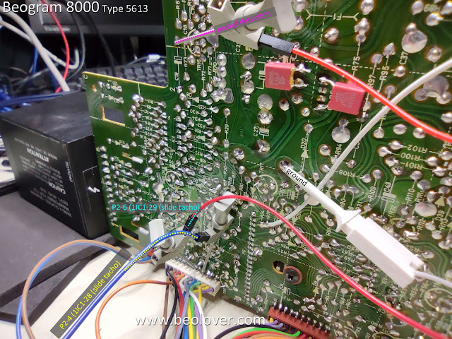
The steady state voltage level of the two LDR devices (forward and reverse) should be around 620 millivolts (DC). I like to set them at around 650 mVdc. They are dialed in by an adjustment screw that affects the amount of light to the sensor.
The adjustment screws are a rather coarse adjustment and is why I installed the little test connector to make tweaking the setting easier (especially after the Beogram 8000 is fully reassembled in its cabinet).
Here are the forward and reverse, steady-state measurements for the LDR devices.
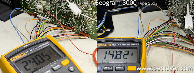
I also measured the +5 VDC, +15 VDC and -15 VDC power supplies again.
I measured the +5 VDC at the filter capacitor inside the PCB 2 assembly that supplies power to the microcomputer (uC).
I checked the +15 VDC voltage going into the regulator and coming out of the regulator.
I measured the -15 VDC off the 1TR19 collector where that voltage regulation output is located.
From there I moved to making some measurements on the oscilloscope of the speed sensor, the two position sensors and the record detection sensor.
For the speed sensor I measured the raw signal coming off the sensor assembly, then at uC (2UI1-40) after the signal has been filtered.
Here is the measurement point for the raw signal from the sensor assembly (P4 pin 7).
Here is the measurement point on 2IC1-40 (uC).
...and here is what the oscilloscope shows.
Next are the measurements for the two position sensor signals and the record detector signal.
I made those measurements with the tangential arm assembly moving forward and in reverse.
Here are the measurement points.
...and the oscilloscope measurements.
The supply voltages and sensors all looked good so I moved to the final two adjustments on this Beogram 8000.
The first adjustment was to check the phono cartridge tracking force and adjust it if necessary.
The second adjustment was to set the sensitivity of the tangential tracking sensor.
For both of these adjustments I need the Beogram 8000 where I can operate it but I don't want the platter to rotate. With a belt driven turntable it is just a matter of removing the belt.
On the Beogram 8000 it means disconnecting the P4 connector on PCB 1.
Just to be safe, disconnect and connect the cables with the Beogram unplugged from the wall.
The tracking force and tracking sensitivity are both adjusted on the tonearm assembly.
The tracking force for the phono cartridge is always available for the owner to set using the small adjustment slider under the tracking force scale (along the side of the tonearm).
What I do during the service manual checks is calibrate the tracking weight so it is as close to 1 gram as I can get it with the slider set to "1" on the scale.
To do that I use a digital scale and adjust the tracking force counter-weight position as necessary to get 1 gram on the measurement.
Note: I make the tracking force measurement with the platter turned upside-down because it is flat enough for the measurement scale to rest on.
On the tracking sensitivity adjustment the procedure is to place a test record on the platter, then advance the tonearm over a test track (usually in the middle of the record) and set the arm down.
I also set the arm down (with a phono cartridge attached) before that and make sure that the tracking sensitivity isn't too sensitive where the arm starts moving forward by itself.
The arm should lower straight down and the phono stylus sits in the record groove with no forward advancement of the servo motor (that drives the tonearm assembly).
Next, the platter is manually rotated and the servo motor is observed for movement.
The servo motor should advance the arm within one or two revolutions of the platter to begin with, then every platter revolution after.
Should the tracking sensitivity require adjustment, there is a small adjustment screw on the side of the tangential arm assembly...shown here.
That completes the Beogram 8000 adjustments. Now it was time to actually play a record.
I will do more complete record play testing later, when the Beogram 8000 is fully assembled.
At this point however, I like testing record play with my Workshop Beomaster 8000.
Besides being anxious to listen to a record, now is a good time to check the record play functions.
If there was a problem, the Beogram 8000 is already open for trouble-shooting.
I like testing with a Beomaster 8000 because the two components are integrated with their controls.
Pressing Play on the Beogram 8000 will cause the Beomaster 8000 to turn on and switch to the phono (PH) source. Pressing PH on the Beomaster 8000 will cause the Beogram 8000 to start playing a record.
Note: I keep my Workshop Beomaster 8000 opened up for servicing at all times so I can use it for Beomaster 8000 board testing. Just like I keep my Workshop Beogram 8000 opened up.
The first record play test performed perfectly so I just relaxed and finished the day listening to some vinyl.


No comments:
Post a Comment
Comments and suggestions are welcome!