Featured Post

Beolover SyncDrive: DC Platter Motor Replacement for Beogram 4002 and 4004 (Type 551x and 552x)

Late Beogram 4002 and the 4004 (Types 551x and 552x), which have DC platter motors instead of the earlier synchronous AC motors usually suff...

Showing posts with label Beogram 8000 Type 5613. Show all posts

Friday, June 16, 2023

Beogram 8000 Type 5513: Tomball Texas Project Completed

This nice Beogram 8000 project is now complete and is ready to return to its owner.

The last few tasks were some simple tasks like re-attaching the deck panel that fits underneath the tonearm.


The dust cover was in good shape but in the right light I could see some scratches that I felt a quick buffing would clean up.

The picture on the left is before doing any polishing.  The photo on the right is after some light buffing with the mildest polish I have.


There was already an improvement.

With a little bit more polishing the Beogram 8000 was ready to move to my listening room.
I think it looks really good.


Now for the fun part...the listening tests.
I like that a lot of the new record pressings are in colorful vinyl.  They look good spinning on the platter :-)


Monday, June 5, 2023

Beogram 8000 Type 5513: Tomball Texas Project Final Adjustments and First Record Play

The Beogram 8000 restoration project from Tomball, Texas is playing records again.

To get to this point I had to perform some remaining adjustments.

First was the forward/reverse scanning LDR adjustments.  Those are for the tonearm forward and reverse buttons on the control panel.  The Beogram 8000 uses a couple of LDR devices (resistors that change value when light hits them) and a rocker spring that is an aperture for the light source to strike the LDR.
The steady state voltage level of the two LDR devices (forward and reverse) should be around 620 millivolts (DC). I like to set them at around 650 mVdc. They are dialed in by an adjustment screw that affects the amount of light to the sensor.  

The adjustment screws are a rather coarse adjustment and is why I installed the little test connector to make tweaking the setting easier (especially after the Beogram 8000 is fully reassembled in its cabinet).

Here are the forward and reverse, steady-state measurements for the LDR devices.


I also measured the +5 VDC, +15 VDC and -15 VDC power supplies again.
I measured the +5 VDC at the filter capacitor inside the PCB 2 assembly that supplies power to the microcomputer (uC).


I checked the +15 VDC voltage going into the regulator and coming out of the regulator.


I measured the -15 VDC off the 1TR19 collector where that voltage regulation output is located.


From there I moved to making some measurements on the oscilloscope of the speed sensor, the two position sensors and the record detection sensor.

For the speed sensor I measured the raw signal coming off the sensor assembly, then at uC (2UI1-40) after the signal has been filtered.

Here is the measurement point for the raw signal from the sensor assembly (P4 pin 7).


Here is the measurement point on 2IC1-40 (uC).


...and here is what the oscilloscope shows.


Next are the measurements for the two position sensor signals and the record detector signal.
I made those measurements with the tangential arm assembly moving forward and in reverse.

Here are the measurement points.


...and the oscilloscope measurements.


The supply voltages and sensors all looked good so I moved to the final two adjustments on this Beogram 8000.

The first adjustment was to check the phono cartridge tracking force and adjust it if necessary.
The second adjustment was to set the sensitivity of the tangential tracking sensor.

For both of these adjustments I need the Beogram 8000 where I can operate it but I don't want the platter to rotate.  With a belt driven turntable it is just a matter of removing the belt.
On the Beogram 8000 it means disconnecting the P4 connector on PCB 1.  

Just to be safe, disconnect and connect the cables with the Beogram unplugged from the wall.


The tracking force and tracking sensitivity are both adjusted on the tonearm assembly.


The tracking force for the phono cartridge is always available for the owner to set using the small adjustment slider under the tracking force scale (along the side of the tonearm).
What I do during the service manual checks is calibrate the tracking weight so it is as close to 1 gram as I can get it with the slider set to "1" on the scale.

To do that I use a digital scale and adjust the tracking force counter-weight position as necessary to get 1 gram on the measurement.

Note: I make the tracking force measurement with the platter turned upside-down because it is flat enough for the measurement scale to rest on.


On the tracking sensitivity adjustment the procedure is to place a test record on the platter, then advance the tonearm over a test track (usually in the middle of the record) and set the arm down.
I also set the arm down (with a phono cartridge attached) before that and make sure that the tracking sensitivity isn't too sensitive where the arm starts moving forward by itself.

The arm should lower straight down and the phono stylus sits in the record groove with no forward advancement of the servo motor (that drives the tonearm assembly).

Next, the platter is manually rotated and the servo motor is observed for movement.
The servo motor should advance the arm within one or two revolutions of the platter to begin with, then every platter revolution after.

Should the tracking sensitivity require adjustment, there is a small adjustment screw on the side of the tangential arm assembly...shown here.


That completes the Beogram 8000 adjustments.  Now it was time to actually play a record.

I will do more complete record play testing later, when the Beogram 8000 is fully assembled.
At this point however, I like testing record play with my Workshop Beomaster 8000.
Besides being anxious to listen to a record, now is a good time to check the record play functions.
If there was a problem, the Beogram 8000 is already open for trouble-shooting.

I like testing with a Beomaster 8000 because the two components are integrated with their controls.
Pressing Play on the Beogram 8000 will cause the Beomaster 8000 to turn on and switch to the phono (PH) source.  Pressing PH on the Beomaster 8000 will cause the Beogram 8000 to start playing a record.

Note: I keep my Workshop Beomaster 8000 opened up for servicing at all times so I can use it for Beomaster 8000 board testing. Just like I keep my Workshop Beogram 8000 opened up.

The first record play test performed perfectly so I just relaxed and finished the day listening to some vinyl.


Monday, May 29, 2023

Beogram 8000 Type 5513: Tomball Texas Project Floating Chassis Work

With the Beogram 8000 circuit board restoration complete, it is time to get the floating chassis in shape to test them with.  In the previous post I tested the restored PCBs with my Workshop Beogram 8000.  My goal here was to be able to test the basic Beogram 8000 functions with all of its own components.

The Beogram 8000 floating chassis has a couple of electrolytic capacitors that needed replacing.
Both are for the +5 VDC power regulation circuit.

Here is the before photo.


Here is the after photo.


The floating chassis also has the phono muting relay circuit.
The muting relay often is still functional but after forty plus years of operation I go ahead and replace it.

Here is the original phono muting relay.


Most of the Beogram 8000 units I have seen have this National HB2-DC12V-H5 relay.
Unfortunately, it is no longer produced so my solution is to use Beolover's HB2 replacement for the Beogram 400x turntable, an Omron G6K-2F device mounted on a customer adapter board.  That requires a little bit of modification though.
The Beogram 400x turntable relays operate at 24V instead of 12V which is required on the Beogram 8000.  Luckily, the Omron G6K-2F relay comes in 12V as well as 24V.  So that can easily be changed on the Beolover relay assembly.  

One other modification to the Beolover replacement relay is to invert the PCB mounting posts.  The position of the polarity on the Beogram 8000 circuit is mirrored to the normal mounting of the Beolover replacement relay device.  Another easy modification though and here is the Beolover relay assembly re-configured for use in the Beogram 8000.


The last bit of restoration work that requires using a soldering gun is the modification I always make to the Beogram 8000 control panel.

The control panel needs to be opened up anyway to clean out dust.
It is pretty common to find a Beogram 8000 control panel with broken mounting tabs for the button PCB to the control panel buttons.  This Beogram 8000 has a fully intact control panel.

For that reason I will show some photos of how to disassemble the control panel.

Here is the starting point...a fully intact Beogram 8000 control panel.


One small screw keeps the button circuit board in place on the control panel.
To disassembly the control panel, the small screw is removed, then the right edge of the board is raised slightly so the mounting hole clears the small mounting post the screw was attached to.
The button panel should be carefully slid to the right as the right edge is lifted.
Once the screw mounting post is cleared, the button circuit board will lift right off.


Here is the control panel disassembled for cleaning (and attaching my LDR test connector).


I started attaching a test connector for the control panel LDRs a while back because I wanted a quick way to check them again when the Beogram 8000 is all put together back in its cabinet.  It is a pain to open up the Beogram into service position again just to measure the LDR voltages.

Here is the reassembled control panel with the test connector.


The test connector can be accessed for testing the control panel LDRs simply by opening the control panel by itself...while the rest of the Beogram 8000 is closed up.

The next steps in this restoration were to work on the platter hub (tachodisc replacement) and cleaning, adjusting the tangential arm assembly.

This Beogram 8000 looks like it still has a functioning tachodisc, but it is the original plastic (decal) kind and is already showing some signs of bubbling in the plastic decal.  I replaced it with a new, metal tachodisc from Beoparts.


Just a bit of warning...changing the tachodisc looks easier than it actually is.
The tachodisc and its mounting ring need to fit tight, and they do.
You have to go slow and be patient to get the old tachodisc off and the new one properly installed where is fits perfectly flat.

On to the tangential arm assembly.

Before lubrication and full reassembly.  This is a good time to perform the adjustment of the arm alignment.

The Beogram 8000 service manual specifies that the top of the fixed arm (and tonearm) should be 23 mm from the top surface of the platter.  That is similar to a Beogram 4002/4004 height adjustment.
However, while the platter height can actually be raised and lowered (a bit) on the Beogram 400x turntables, it cannot on a Beogram 800x turntable.

That means that the vertical tracking angle (VTA) on a Beogram 8000 is fixed.  The arm height adjustment of 23 mm to the platter surface is purely cosmetic...but with B&O components, cosmetics are an important part.  They must perform good and look good.

This arm height adjustment often takes several iterations when doing it with the tangential arm assembly fully assembled.  With the spindle removed, it is easy to just slide the tangential arm assembly manually to make the height measurement between arm adjustments.

Here is the adjusted arm height.


Another reason to make these arm adjustments now is if the tonearm requires any height adjusting to align with the fixed arm.

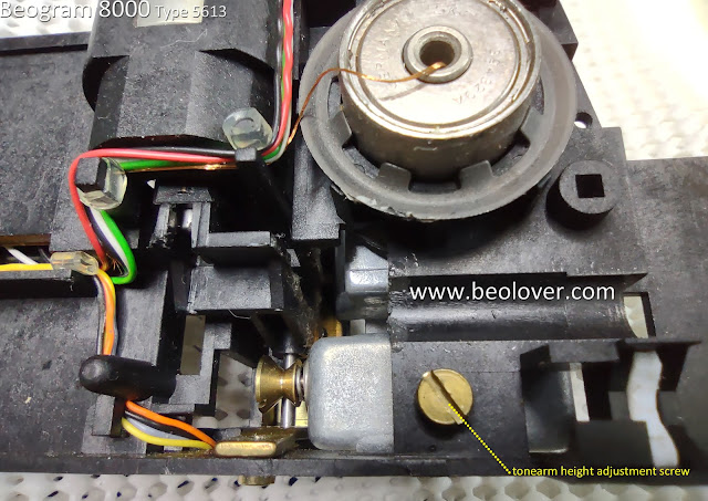
The adjustment screw for the tonearm height is inconveniently located on the underside of the tangential arm assembly which makes it a real pain to adjust later...it means removing the arm assembly again for the adjustment.  So now is the time to do it.


There is one other important tonearm related task while the arm assembly is open.

A common complaint of Beogram 8000 owners is that the Beogram starts dropping the arm onto a record instead of gently lowering it. Most of the time this is because the tonearm height adjustment screw touches the metal base of the tonearm (where the counter-weight is).  For some reason the arm lowering mechanism slowly lowers (via the solenoid) but the arm itself delays and does not follow it.
Then, suddenly, the arm drops down as the screw releases from contact with the base of the tonearm.
It is not magnetic as the adjustment screw is brass.  Nevertheless, I have witnessed this happening.
My solution is similar to what B&O does on the Beogram 400x tonearm lowering mechanism.  I place a thin piece of plastic material (Dura-Lar) between the height adjustment screw and the base of the tonearm.


This modification has always worked for me.

Moving on...Here are the tangential arm assembly main parts removed and cleaned.


For mounting the spindle back onto the floating chassis, I use some red grease for the two mounting ends.

For the two rails, I use some dry lubricant for the shiny, smooth rail surface.

For the spindle itself, I have plenty of the original lubricant mixture called out in the B&O service manual.  That is Rocol MTS grease mixed with Esso NUTO oil.
I have mentioned this before, I use this mixture because I happen to have it. If I didn't have it, there are modern, synthetic oil substitutes that can be used.  Just remember to not over do it when oiling the spindle.
The spindle spins so too much oil will result in oil being distributed all over the inside of the Beogram as the spindle turns.

Here is a photo of a test fitting of the cleaned tangential arm components prior to lubrication.


Reassembling the tangential arm spindle, spindle nut, bracket and rear rail can also test your patience a bit.  I like to test fit it before doing it with oil applied.


Here is the tangential arm assembly reinstalled on the floating chassis.


I combined all of the components for this Beogram 8000 for a quick test of some basic functions (Play start, platter scanning, speed adjusting, return to Stop).

Everything I wanted to check worked.


Very nice to see.  A major milestone in this restoration.

For the next post I will make the necessary service manual adjustments to prepare for record play and perform the first test play of a record.

Saturday, May 27, 2023

Beogram 8000 Type 5513: Tomball Texas Project Electronic Work

The main electrical restoration work has been completed successfully on this Beogram 8000 from Tomball, Texas.

I changed out the old capacitors on PCB1 (including daughter boards PCB6 and PCB7), PCB2 and the Transformer Assembly.  I also changed out the microcomputer (uC) 40-pin socket in PCB2.

Here is the Beogram 8000 Transformer Assembly.
As named, it is the transformer for the Beogram but, for extra space savings, Bang & Olufsen used the Transformer Assembly box to house the 27uF, non-polar, electrolytic capacitor - C1 ...4C1 actually.


This old C1 capacitor measures 39uF instead of 27uF as shown on the capacitor...quite a bit out of tolerance.

I replaced it with two 56uF polarized capacitors in series to get close to 27uF and configured them so they will be non-polar.  That is with the two negative leads connected to each other.
I also mounted them in the transformer box using our Beolover 3D printed assembly.


The actual capacitance of this custom assembly measured 29uF so that is good.

I worked on the PCB2 assembly next.  That is the assembly that houses the micromputer (uC) IC.
Here is another photo of PCB2 before restoration.


As highlighted in the photo, capacitor C28 is the only electrolytic capacitor in this PCB.  It is part of the +5VDC supply voltage circuit for the uC.
One important note about replacing this capacitor is that the positive lead for the capacitor is soldered on the underside (trace side) of PCB2.  The negative side however, is soldered on both sides of PCB2.
Failure to solder the negative lead to ground on both sides of the board will cause the board to not work.

Here are some photos of the PCB2 restoration.


PCB2 and the Transformer Assembly are done.

Now on to PCB1 (and its related daughter PCBs: PCB6 and PCB7).

Here is the photo of PCB1 from my initial assessment post.


I didn't notice it at the time but once I started the restoration work on it I could see that capacitor 7C3 (of the Control for uC daughter-board) was completely blown.


That doesn't change anything regarding this restoration...it just confirms that these aging capacitors are often at the limit.

Here are some pictures of the other PCB1 capacitors prior to their replacement.


The next set of photos are after the capacitors were replaced.


For the +24 VDC power supply filter capacitor, 1C27, I like to remove the three-pronged base (which is the ground lead for 1C27) and re-use it on the replacement capacitor for 1C27.


Before continuing on and doing the restoration work on the floating chassis components and control panel, I decided that I couldn't wait for that to check out this electrical work so far.

I reassembled the PCB1 and PCB2 boards and checked them out on my Workshop Beogram 8000.
That is why I have that unit...it provides a nice tool to check out other Beogram 8000 boards.

The first power on is often an anxious moment but I was very confident these boards would work good.
While a majority of the original capacitors were out of tolerance, including that one, blown capacitor, this set of boards is in fantastic shape. The solder joints are all nice.  The board connectors are solid and great.  The ribbon cables plug into the connectors firmly and fit perfect.

Sure enough, plugging the Workbench Beogram 8000 in with this set of restored boards showed that they are working as they were designed.

Pressing Play, the Beogram searched the empty platter for a record, automatically switched from 33 RPM to 45 RPM at the correct position, then returned to Standby mode.


It always feels good after success like this.

The next steps will be to do all of the work on the floating chassis components and the control panel.
Once those are ready, I will connect those up with these completed boards and do a full functional test.
I will also measure voltages and check sensor signals at that point.