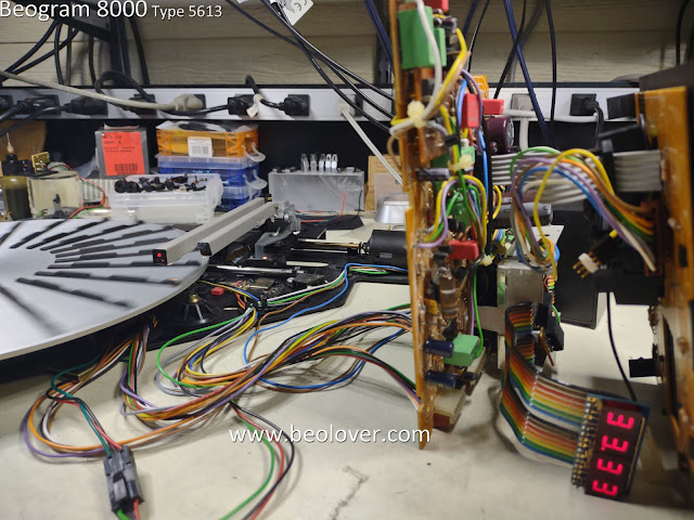
The main electrical restoration work has been completed successfully on this Beogram 8000 from Tomball, Texas.
I changed out the old capacitors on PCB1 (including daughter boards PCB6 and PCB7), PCB2 and the Transformer Assembly. I also changed out the microcomputer (uC) 40-pin socket in PCB2.
Here is the Beogram 8000 Transformer Assembly.
As named, it is the transformer for the Beogram but, for extra space savings, Bang & Olufsen used the Transformer Assembly box to house the 27uF, non-polar, electrolytic capacitor - C1 ...4C1 actually.
This old C1 capacitor measures 39uF instead of 27uF as shown on the capacitor...quite a bit out of tolerance.
I replaced it with two 56uF polarized capacitors in series to get close to 27uF and configured them so they will be non-polar. That is with the two negative leads connected to each other.
I also mounted them in the transformer box using our Beolover 3D printed assembly.
The actual capacitance of this custom assembly measured 29uF so that is good.
I worked on the PCB2 assembly next. That is the assembly that houses the micromputer (uC) IC.
Here is another photo of PCB2 before restoration.
As highlighted in the photo, capacitor C28 is the only electrolytic capacitor in this PCB. It is part of the +5VDC supply voltage circuit for the uC.
One important note about replacing this capacitor is that the positive lead for the capacitor is soldered on the underside (trace side) of PCB2. The negative side however, is soldered on both sides of PCB2.
Failure to solder the negative lead to ground on both sides of the board will cause the board to not work.
Here are some photos of the PCB2 restoration.
Now on to PCB1 (and its related daughter PCBs: PCB6 and PCB7).
Here is the photo of PCB1 from my initial assessment post.
I didn't notice it at the time but once I started the restoration work on it I could see that capacitor 7C3 (of the Control for uC daughter-board) was completely blown.
That doesn't change anything regarding this restoration...it just confirms that these aging capacitors are often at the limit.
Here are some pictures of the other PCB1 capacitors prior to their replacement.
The next set of photos are after the capacitors were replaced.
For the +24 VDC power supply filter capacitor, 1C27, I like to remove the three-pronged base (which is the ground lead for 1C27) and re-use it on the replacement capacitor for 1C27.
Before continuing on and doing the restoration work on the floating chassis components and control panel, I decided that I couldn't wait for that to check out this electrical work so far.
I reassembled the PCB1 and PCB2 boards and checked them out on my Workshop Beogram 8000.
That is why I have that unit...it provides a nice tool to check out other Beogram 8000 boards.
The first power on is often an anxious moment but I was very confident these boards would work good.
While a majority of the original capacitors were out of tolerance, including that one, blown capacitor, this set of boards is in fantastic shape. The solder joints are all nice. The board connectors are solid and great. The ribbon cables plug into the connectors firmly and fit perfect.
Sure enough, plugging the Workbench Beogram 8000 in with this set of restored boards showed that they are working as they were designed.
Pressing Play, the Beogram searched the empty platter for a record, automatically switched from 33 RPM to 45 RPM at the correct position, then returned to Standby mode.
It always feels good after success like this.
The next steps will be to do all of the work on the floating chassis components and the control panel.
Once those are ready, I will connect those up with these completed boards and do a full functional test.
I will also measure voltages and check sensor signals at that point.


No comments:
Post a Comment
Comments and suggestions are welcome!