I used that capability to check out my completed restoration tasks so far.
I wanted to see what works and what doesn't work on this turntable after my initial work.
The first thing to check is the power supply so I assembled the parts and plugged the transformer in to the wall.
Most of the time on this type of restoration I immediately get the little, red Standby dot on the display when I plug in the Beogram for the first time.
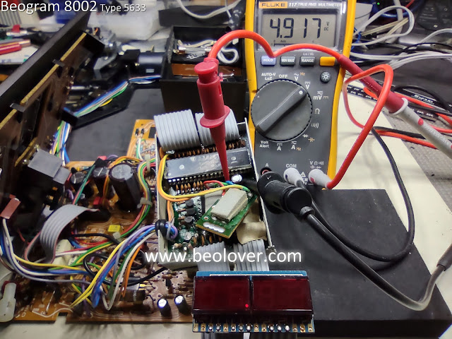
In this case, it was blank...but as you can see in the photo, I was measuring the +5V regulator and it does show a proper voltage.
So this was some connection problem.
Checking the other Beogram 8002 supply voltages I found that everything had power.
Here is the +24V across the 1C27 filter capacitor.
Here is the -24V across the 1C29 filter capacitor.
The 1C24 capacitor measured around 13V that goes to the +5V regulator.
...and the regulated +5V signal to PCB 1 is good.
The problem was that the +5V power was not reaching the 2C28 capacitor on PCB 2.
That wasn't too surprising as connection problems do occur with these turntables.
One item I have never been fond of with the Beogram 8002 (and 8000) design is the PCB 1 P6 connector and ribbon cable to PCB 2.
It is a press-to-fit connector and often times the ribbon cable does not feel like it mates securely enough.
That was the case here.
Re-seating the cable a couple of times allowed me to finally get the Beogram 8002 to come on in the Standby mode.
I didn't want to leave it like this though.
It would be too easy for the cable to lose a connection again.
I decided to cut away more material from the channel areas of the ribbon cable so I could seat the cable further into the P6 connector.
That worked much better and the cables don't just fall out of the connector like they did before.
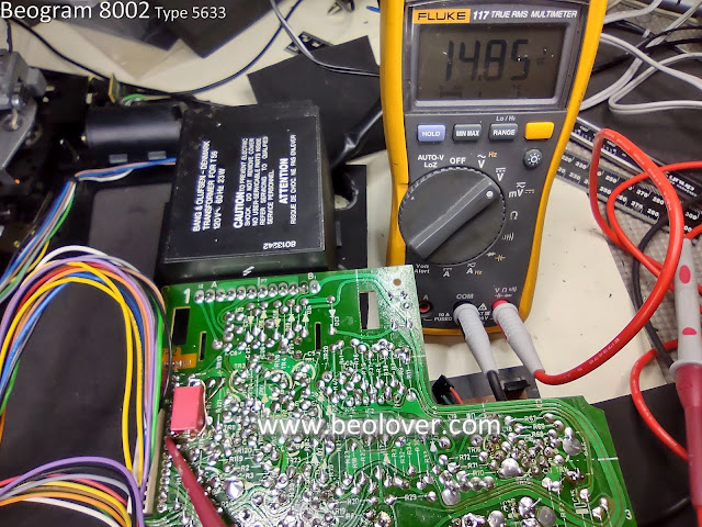
Now that the Microcomputer board has proper power I can turn the Beogram 8002 on and check the ±15V regulated supplies.
They both look good.
Moving on, I checked the platter drive and observed that the 33.33 and 45 RPM speeds worked.
I also tested the arm lowering and the solenoid control mechanism appears to work great.
That was just a quick set of tests to see if there are any major problems with the restoration so far.
There doesn't appear to be so I will move on to checking the various sensor signals on the Beogram 8002 and make sure they are working properly.
There doesn't appear to be so I will move on to checking the various sensor signals on the Beogram 8002 and make sure they are working properly.


No comments:
Post a Comment
Comments and suggestions are welcome!