Featured Post

Beolover SyncDrive: DC Platter Motor Replacement for Beogram 4002 and 4004 (Type 551x and 552x)

Late Beogram 4002 and the 4004 (Types 551x and 552x), which have DC platter motors instead of the earlier synchronous AC motors usually suff...

Showing posts with label adjusting. Show all posts

Saturday, May 19, 2018

Beomaster 6000 (2702) restoration: final assembly and testing

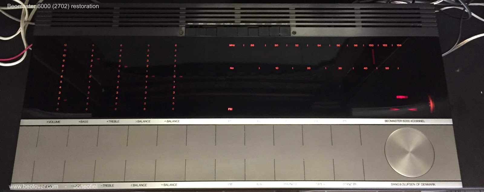
After some delay caused by the need to recoat the key panel (see update here), it is now finally time to finish the assembly and start testing the Beomaster 6000 quad after this full restoration!

The display panel for the volume, tone and balance controls needs to be as close as possible to the red plexi panel for good readability. Therefore the frame on which the the display panel, motor controls, pulleys, clutches, tone amplifier PCB is mounted is adjustable. On each side on the frame there are 3 M3 bolts:  the middle one is to lock the adjustment and with the two other screws you can tilt and raise the frame.

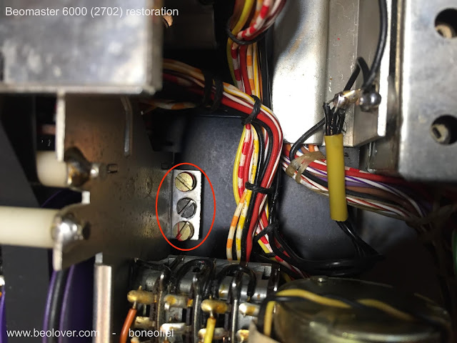


Since you can not reach these bolts once the plexi panel is back in place, a different method is needed. I first attached the back black frame and the complete key panel to the main chassis. This was to have a reference point for adjusting.


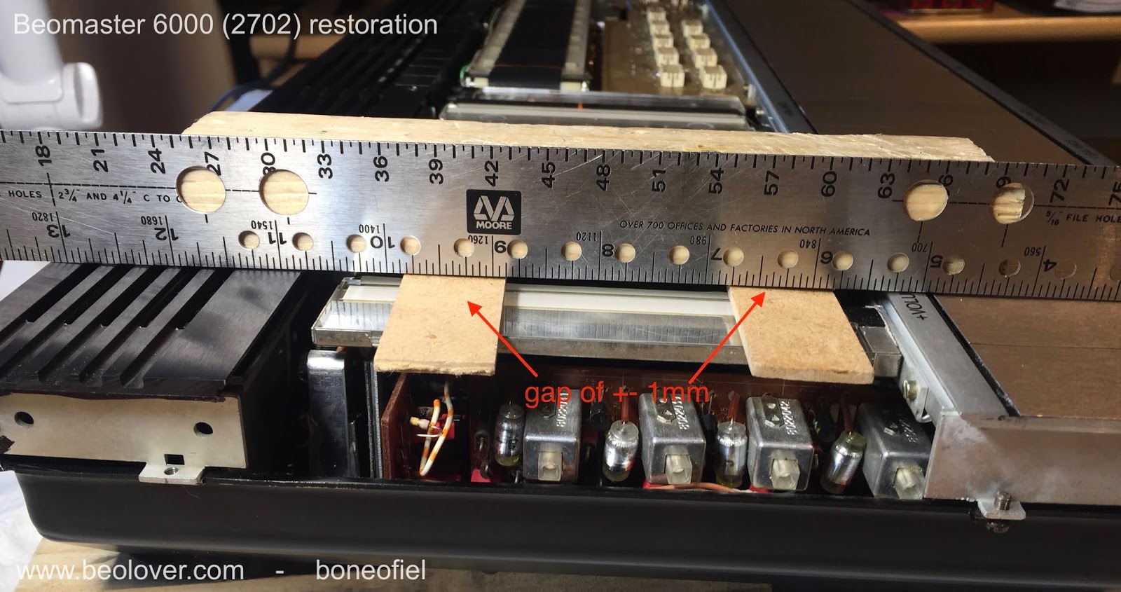
I used a metal ruler and some pieces of wood (with the same thickness as the plexi panel) to make the adjustment.


An air gap of about 1mm is sufficient to leave enough room for the display bands to move freely and avoid rubbing.
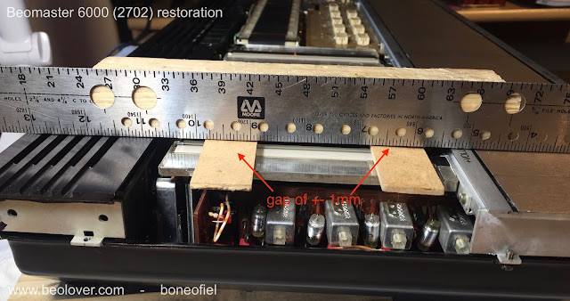


Once this is done the keypanel temporary screws are removed and the plexi panel is put in place. The next step is to attach the wood plinth and the keypanel.


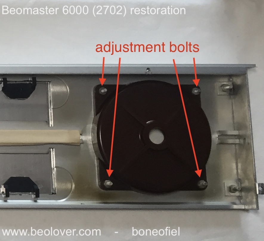
One last adjustment, before tightening the keypanel and the wood plinth, is the centering of the FM dial spindle/flywheel. This is needed because the keypanel had been removed for coating and glued back. There is always a bit of play. The spindle is rotating in two ball bearings. The top one is fixed in the square plastic holder just under the spindle. The square plate first need to be centered by loosening the 4 M3 nuts.


The second ball bearing is inside the shaft bushing at the bottom. This ball bearing is in a metal bushing that is adjustable with 3 bolts. If you loosen these 3 bolts the whole spindle can "wobble" a bit and allows to have the spindle surface flat and centered with the surrounding aluminium frame. This can only be done once the keypanel with the wood plinth is firmly fixed.


And finally the wire bracket is put in place.


Time for testing ! I attached 2 Beovox S45-2 as front speakers and 2 Beovox P45 as rear speakers. I also attached an Airplay device to play some music from my iPad.
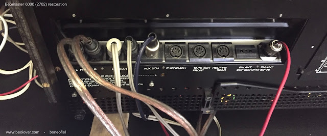


And I had sound on all 4 speakers !!!!! 


A reflexion after this many, many hours of careful restoration of this iconic Beomaster 6000 quad: it's not a job for the faint of heart ! Was it a succes? Yes, definitely. Does it look and sound good? It sounds sweet to my ears. And it looks as good as one can imagine after some 40+ years of use. I've been at the Bang & Olufsen museum in Struer, Denmark, where there is (off course) one of these units on display (and fully operational). See picture below. And honestly, mine looks better ! 

I will now let it play for some days/weeks before I'll ship it to his new owner. 


Above picture is courtesy of the B&O Museum in Struer, Denmark.

Wednesday, January 24, 2018

Beomaster 8000: Output Amplifier Board Initial Testing

The Beomaster 8000 Output Amplifier boards are recapped and the output transistors have been remounted with new thermal insulators. Before using these amplifier boards they need to be checked out and the no-signal current level adjusted to 18mV across the emitter resistors. I will do a final check again on these once the boards are re-installed in the Beomaster cabinet but while the boards are out it is good to do an initial check.

This check will let me know if there are any serious problems before going to the trouble of re-installing the boards.

For this test outside the Beomaster I need ±55VDC power and +15VDC power to the board. I also need a multi-meter to measure the voltage across the emitter resistors.

I can get ±55VDC with my two 0-60 VDC bench power supplies. These supplies are nice because I can set them up to limit their current to 15mA. That will provide protection against burning anything up should there be a hidden short circuit somewhere (i.e. a bad component).

Here is one of the two identical output amplifier boards ready for the no-signal current adjustment.


Adjusting the no-signal current involves slowly ramping up the ±55V rail voltages simultaneously to 55V. This should result in ±55V ready to go on the positive and negative supply rails. The +15V is then slowly applied to P38-2 which controls current in the output amplifier. The current draw from the  ±55VDC supplies should be around 100mA to 110mA when the output amplifier is on (+15 VDC applied to P38-2). The R226 trimmer resistor adjusts the no-signal current of the amplifier.


My bench multi-meter is more accurate for this adjustment than my hand held DMM so I switched to the bench meter to dial in the 18mV emitter voltage setting.


Here is a picture of the bench power supplies with the output amplifier on and the proper no-signal current level set.


I repeated the adjustment for the other output amplifier board and these two boards are ready to be re-installed in the Beomaster.

Friday, July 28, 2017

Beogram 4004 Type 5526: Record Detector Testing and Adjustments

This Beogram turntable has a new LED lamp source for the record detector circuit that is in the fixed arm. Part of that installation involved switching out a fixed 1MOhm resistor (1R26) with a 2MOhm trimmer resistor to allow better tuning of that detector circuit voltage. With the turntable parts re-installed I started the procedure of making an initial setting of the new 1R26 trimmer so the collector of 1TR3 is at 4 VDC when the fixed arm lamp is on.

I made that adjustment then moved the 1R26 trimmer resistor to the component side of the board where it belongs (so it is out of the way of the platter).


A quick test of the Beogram Start, without a record on the platter, passed with the sensor circuit correctly recognizing there was no record on the platter.

To complete this test however it is always a good idea to actually see the signal on an oscilloscope. I connected a probe wire to the 1TR3 collector and then to my scope. When I ran the fixed arm and tonearm over the platter I paused it so I could measure what the detector circuit is seeing.


I was surprised and disappointed to see that the peak to peak voltage of the signal was not from 0 V to around 6 V as expected. It only drops to about 2 V and goes up to 4.72 V.

So while the Beogram appears to detect an empty platter as it should, the signal is not ideal and could lead to problems later on. A little bit less peak to peak voltage and this circuit will not detect an empty platter.

I wanted to know if the problem was in the new Beolover light source assembly or with the fixed arm light sensor. The easy thing to try first was to use a powerful LED flashlight to enhance the light on the platter. When I did that I could make the 1TR3 collector signal go to its full range. But look how much light it took for the sensor to register that. Something must be wrong with the sensor.


As a second part of the test I pulled out the fixed arm lamp and sensor assembly a ways so I could move the Beolover LED module and watch the effect on the 1TR3 collector voltage.


Moving the LED light source could not make the signal peak to peak range any better. It could make it worse though and confirmed my fear that a little less voltage would cause the platter detection to fail.

Next step then is to swap out the fixed arm sensor. I decided to swap out the entire assembly first with one of my spares (from another Beogram 4004 turntable).

Here is the removal of the current sensor assembly that has the Beolover LED light source.


Here is the replacement sensor assembly. It still has an original incandescent light source.


Just like that, the 1TR3 collector signal went right to what is expected. The peak to peak voltage is from 0 V to about 6 V.


That voltage is with a dimmer light source as the Beolover LED light source is brighter than the incandescent lamp. The original fixed arm platter sensor is the problem and will have to be replaced.

Wednesday, July 26, 2017

Beogram 4004 Type 5526: Tangential Arm Position Detector

Just a quick and short update...
I didn't get as much bench time as I wanted the last couple of days but I did sneak on long enough to connect power and adjust the Beogram's tangential arm position detector voltage.

Just like I did on the previous Beogram 4002 (Type 5513) project, I needed to verify that the base voltage of 1TR17 is at a nice 0.7 VDC when the light source 4D1 is illuminating the tangential arm position sensor, 4IC1.

It was a little off so adjusting trimmer resistor 1R88 was necessary to bring the voltage down. This picture shows the initial adjustment.


Once I re-attached the position scale I re-checked the voltage at 1TR17 base with the 4D1 LED at a transparent part of the scale.

I then ran the Beogram tangential arm through some of its operations. Everything worked great.


Later tonight I will measure and adjust the new 2M ohm trimmer for the fixed arm record detector.


Wednesday, April 19, 2017

Beogram 8002: Service Manual Adjustments

Going in to the Beogram 8002 service manual adjustments I already know that the fixed arm and tonearm horizontal parallelism needs adjusting. The tonearm appears higher than the fixed arm as you can see in this picture.


The tops of the two arms should be the same height and that height should be 19.5mm from the top of the Beogram platter. So the fixed arm needs to be adjusted up and the tonearm needs to be adjusted down.

To make all of the necessary adjustments I have to get to the underside of the tonearm carriage assembly. That means removing the rails and the tangential drive screw. I have to do this anyway to clean and re-apply some lubrication.

The red arrow in this picture shows the adjustment screw for the tops of the arms (the horizontal parallelism adjustment). The green arrow is for the vertical parallelism adjustment (the gap between the two arms). I am pointing that out as it turned out I needed to adjust it as well.


After adjusting the horizontal parallelism I got both arms to the 19.5mm height from the platter surface.


I installed a new tangential arm drive belt.


I also cleaned and checked the lubrication of the platter hub. The following pictures show the Beogram from platter hub removed to the sub-platter re-installed. I was able to find a spare tonearm assembly cover trim piece. The original one was missing from this turntable and the wires were exposed.


When I put the top platter back on and connected the main board the tonearm and platter worked okay but I noticed something was not right with the tonearm. When the Beogram 8002 tonearm is at rest you should be able to push the arm towards the fixed arm and have it spring right back to centered position when you let go. With this tonearm I was detecting an obstruction that was hindering the spring back action.

I was concerned at first because I couldn't see anything wrong. The vertical parallelism looked correct. I took a peek into the tangential arm tracking sensor assembly.

Note the spring clip in the picture below. That spring mechanism moves the tonearm back to a centered position when you move the tonearm away from the fixed arm.


Everything was fine in there. Nothing was scraping.

I finally realized the tonearm vertical parallelism adjustment screw was the problem. It had been adjusted incorrectly. While the gap between the fixed arm and tonearm looked fine, the tonearm raise/lowering bar was not operating correctly in the V-shaped channel of the brass adjustment screw.

The following picture of one of my own Beogram 8002 turntables shows the tonearm lift/lowering bar and the V-Channel adjustment screw. The lift bar has a spring mechanism that will attempt to keep the bar pressed down on the V-channel when the arm is in the raised position (not playing). If you manually move the tonearm towards the fixed arm the lift bar rides up one side of the V-channel. When you let go the tonearm should pivot back to a centered position as the spring loaded lift bar returns to the bottom of the V-channel.


On this Beogram 8002 project turntable the lift bar was getting slightly stuck at the top of the V-channel screw when the tonearm was moved towards the fixed arm. By re-adjusting the V-channel screw (which is the vertical parallelism adjustment screw) I was able to get the tonearm back to its normal, springy self.

The tonearm and fixed arms are also vertically parallel to each other.


I test played one complete side of a record and observed the linear tracking working correctly as the stylus remained always centered. I could see the tangential arm assembly motor adjusting the tonearm position pretty much ever half turn of the record. Very nice results after all of that disassembly/reassembly of the Beogram mechanics.

The last check I wanted to make was the voltage level of the light driven sensor in the control panel. This is for the Beogram forward/fast forward and reverse/fast reverse function. After the Beogram has been operating for at least five minutes the voltage of the forward/reverse sensor should be around 620mVDC in its normal state. This check is done my monitoring control panel connector P5-4 to P5-3 (ground) and P5-6 to P5-3 (ground). To adjust the sensor voltage levels there are two screws on the control panel that operate an aperture for the sensor lamp source as seen in the picture below.


The procedure requires checking the voltages at both test points a few times as each screw is adjusted. Each adjustment screw can affect the measurement at both test points. After a few iterations I got the sensor to a satisfactory level.

Tomorrow I will re-assembly the Beogram 8002 (except for the dust cover lids) and do some actual record playing testing.

Friday, September 18, 2015

Beogram 4000: Adjusting the Platter, Cleaning the Panels and Installing a 3D Printed Guiding Washer for the Cabinet

Today, I spent some time detailing the appearance of the Beogram 4000 that is on my bench right now. First I adjusted the platter height and position within the main aluminum panel. This is an important task, since only if the platter is centered and flush with the panels the Beogram looks right. When I got it the platter was way too low (and also so out of center that it was scraping on the panel):


So I adjusted the main bearing and the three suspensions of the chassis until things were right. Visit the original post for two videos that show in detail how to do that properly.

Here is a picture with everything adjusted and cleaned (the panels usually clean up very nicely with Mr. Clean Magic Eraser pads - just wet them a bit and then clean along the brush direction of the panels...):

How lovely! I can't wait until I'll have the hood restored!

While I played with these adjustments, I also rid this Beogram of the front center mounting screw of the plinth. This is a poor design, which they rectified in the later 4002 and 4004 models by installing an eccentric guiding washer instead of the floppy plastic washer and the shoulder bolt. 

Here is an impression of the original setup:

I recently designed a 3D printed replacement of the 4002-style washers, which is now available via the Beolover Shapeways Store. There is also a video about installing them. Here is a picture of the new washer in place:

I usually put a dab of Ballistol on the washers before installing them. That makes the plinth move in smoothly.