After some delay caused by the need to recoat the key panel (see update here), it is now finally time to finish the assembly and start testing the Beomaster 6000 quad after this full restoration!
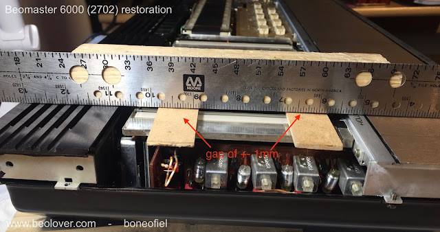
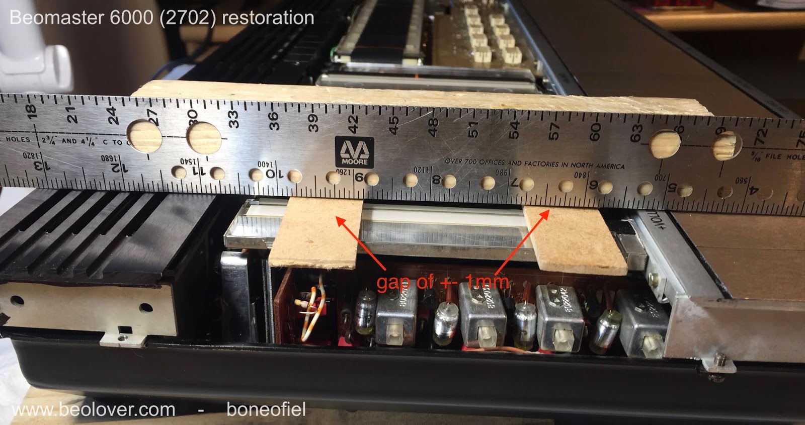
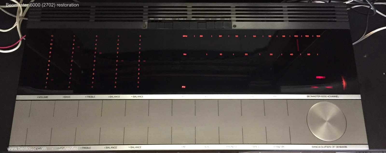
The display panel for the volume, tone and balance controls needs to be as close as possible to the red plexi panel for good readability. Therefore the frame on which the the display panel, motor controls, pulleys, clutches, tone amplifier PCB is mounted is adjustable. On each side on the frame there are 3 M3 bolts: the middle one is to lock the adjustment and with the two other screws you can tilt and raise the frame.


Since you can not reach these bolts once the plexi panel is back in place, a different method is needed. I first attached the back black frame and the complete key panel to the main chassis. This was to have a reference point for adjusting.


An air gap of about 1mm is sufficient to leave enough room for the display bands to move freely and avoid rubbing.
Once this is done the keypanel temporary screws are removed and the plexi panel is put in place. The next step is to attach the wood plinth and the keypanel.
One last adjustment, before tightening the keypanel and the wood plinth, is the centering of the FM dial spindle/flywheel. This is needed because the keypanel had been removed for coating and glued back. There is always a bit of play. The spindle is rotating in two ball bearings. The top one is fixed in the square plastic holder just under the spindle. The square plate first need to be centered by loosening the 4 M3 nuts.

The second ball bearing is inside the shaft bushing at the bottom. This ball bearing is in a metal bushing that is adjustable with 3 bolts. If you loosen these 3 bolts the whole spindle can "wobble" a bit and allows to have the spindle surface flat and centered with the surrounding aluminium frame. This can only be done once the keypanel with the wood plinth is firmly fixed.

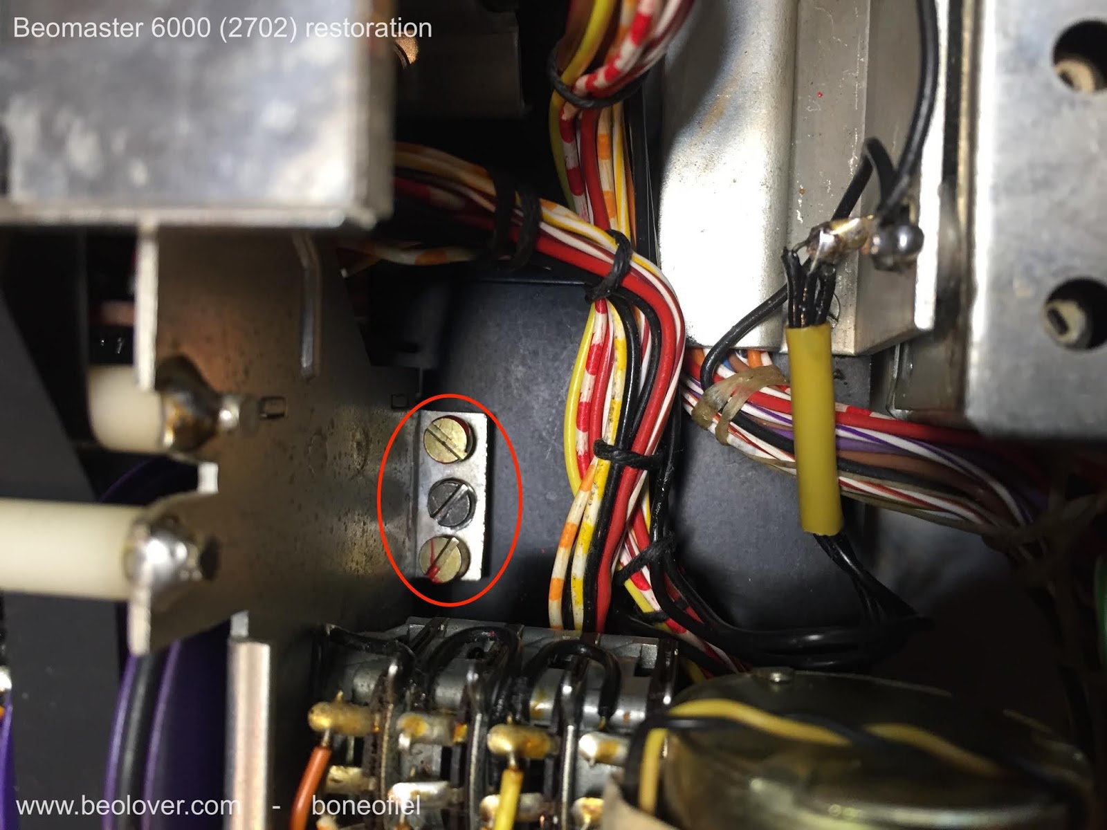
And finally the wire bracket is put in place.


Time for testing ! I attached 2 Beovox S45-2 as front speakers and 2 Beovox P45 as rear speakers. I also attached an Airplay device to play some music from my iPad.

And I had sound on all 4 speakers !!!!!


A reflexion after this many, many hours of careful restoration of this iconic Beomaster 6000 quad: it's not a job for the faint of heart ! Was it a succes? Yes, definitely. Does it look and sound good? It sounds sweet to my ears. And it looks as good as one can imagine after some 40+ years of use. I've been at the Bang & Olufsen museum in Struer, Denmark, where there is (off course) one of these units on display (and fully operational). See picture below. And honestly, mine looks better !
I will now let it play for some days/weeks before I'll ship it to his new owner.

The display panel for the volume, tone and balance controls needs to be as close as possible to the red plexi panel for good readability. Therefore the frame on which the the display panel, motor controls, pulleys, clutches, tone amplifier PCB is mounted is adjustable. On each side on the frame there are 3 M3 bolts: the middle one is to lock the adjustment and with the two other screws you can tilt and raise the frame.

Since you can not reach these bolts once the plexi panel is back in place, a different method is needed. I first attached the back black frame and the complete key panel to the main chassis. This was to have a reference point for adjusting.

I used a metal ruler and some pieces of wood (with the same thickness as the plexi panel) to make the adjustment.

Once this is done the keypanel temporary screws are removed and the plexi panel is put in place. The next step is to attach the wood plinth and the keypanel.
One last adjustment, before tightening the keypanel and the wood plinth, is the centering of the FM dial spindle/flywheel. This is needed because the keypanel had been removed for coating and glued back. There is always a bit of play. The spindle is rotating in two ball bearings. The top one is fixed in the square plastic holder just under the spindle. The square plate first need to be centered by loosening the 4 M3 nuts.
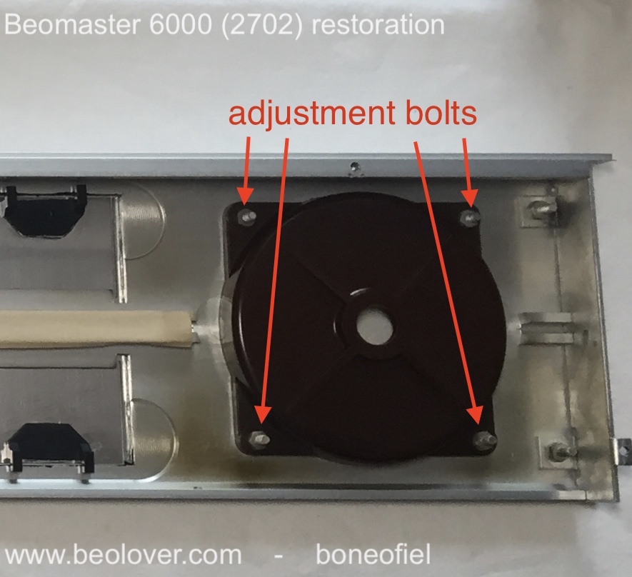
The second ball bearing is inside the shaft bushing at the bottom. This ball bearing is in a metal bushing that is adjustable with 3 bolts. If you loosen these 3 bolts the whole spindle can "wobble" a bit and allows to have the spindle surface flat and centered with the surrounding aluminium frame. This can only be done once the keypanel with the wood plinth is firmly fixed.

And finally the wire bracket is put in place.


Time for testing ! I attached 2 Beovox S45-2 as front speakers and 2 Beovox P45 as rear speakers. I also attached an Airplay device to play some music from my iPad.
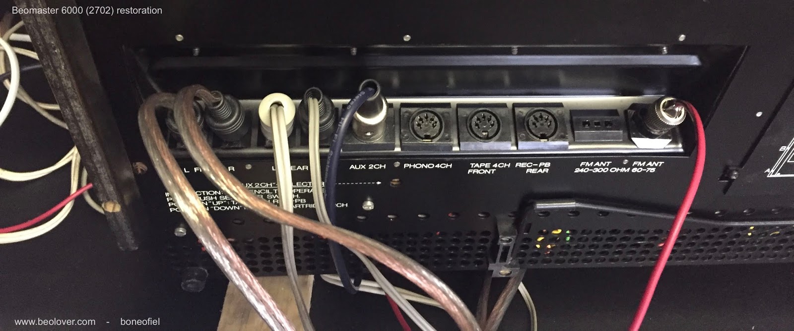
And I had sound on all 4 speakers !!!!!

I will now let it play for some days/weeks before I'll ship it to his new owner.

Above picture is courtesy of the B&O Museum in Struer, Denmark.
No comments:
Post a Comment
Comments and suggestions are welcome!