Per Beolover's explanation here and his repair technique here I temporarily installed a 2M ohm trimmer resistor on the trace side of the main board so I can easily make the initial adjustment. I will do that adjustment later when I get ready to test these current changes.
This picture shows the original 1M ohm resistor (R26) that will get replaced.


Here is the replacement 2M ohm trimmer installed in its temporary location until the adjustment procedure can be made.

As I moved on to install the Beolover replacement module for the tangential tracking I noticed something wrong with the arm lowering solenoid. I didn't notice the problem when I was busy working on the damper but here in this picture you can clearly see that the solenoid is missing its plunger.


To fix the solenoid I removed all of the arm damping components again and will leave them out while I work on the rest of the tangential arm assembly. Having the chassis clear of those components will make working in there a little easier.
Here is the removal of the original tracking sensor assembly. The Beolover replacement part will fit right in place of the original light source housing and the original parts will be saved in case someone wants to revert back to them in the future.
That looks great. Now on to the drive screw cleaning and lubricating.
The drive screw bearing nut and housing always gets dirty over time. This one is no exception. There are even some specs of debris from the disintegrated chassis lock down bushings. Those pieces continue to show up.

I completely remove the drive screw and parts for cleaning and re-lubricating.


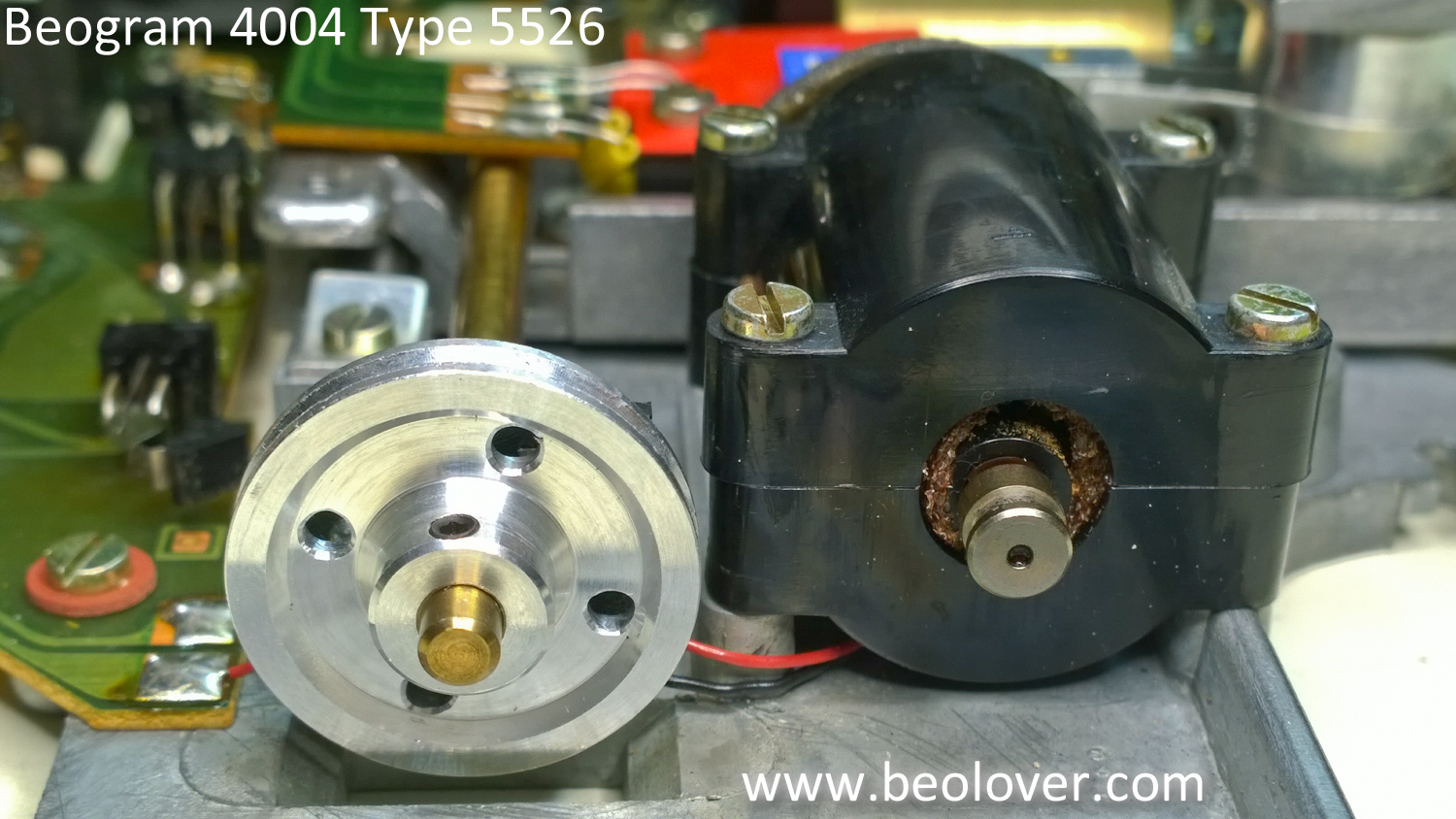
This is the point in the restoration where I also replace the tangential drive pulley. This picture shows the pulley options. I like to replace these Beogram 400x drive pulleys with aluminum replacements from Nick (contact us if you want to get in touch with him).
The aluminum pulley on the left is Nick's original replacement (version 1). The black plastic pulley on the right is the original Beogram 4004 pulley. The pulley I am currently going with is Nick's Version 2 aluminum pulley (the one in the center of the picture). It is a nicer reproduction of the original pulley and is lighter weight than the Version 1 pulley. The indention of the middle area of the pulley also prevents accidental contact with the drive screw mounting bracket screws. A really super nice upgrade.

Here is the drive screw re-assembled with the new pulley.
I will go ahead and note it here that the tangential drive motor on this unit seems a little loose in its housing. I will look at that more closely when I get the Beogram put back together for testing. If I have to I will change out that motor.
Next I put the arm lowering parts back in place. The solenoid plunger is where it should be now.

I made one more electrical change on this Beogram tangential drive assembly while I had it out of the box. Like the recent Beogram 4002 restoration I changed out the old light source for the arm position sensor. The new LED light source will insure there won't be any problems with the old light source failing later. I also took the opportunity to clean the contacts of the tangential arm position switches (shown by the red arrows).


That pretty much does it for the tangential drive electrical restorations. All that I need to do before re-assembling these parts for testing is to align and balance the tonearm.
No comments:
Post a Comment
Comments and suggestions are welcome!