Featured Post

Beolover SyncDrive: DC Platter Motor Replacement for Beogram 4002 and 4004 (Type 551x and 552x)

Late Beogram 4002 and the 4004 (Types 551x and 552x), which have DC platter motors instead of the earlier synchronous AC motors usually suff...

Showing posts with label Beogram 8002. Show all posts

Friday, April 9, 2021

Beogram 8002: Arm Moves a Few mm and Then Stops - Replacement of Photo Resistors and Bulb in the Keypad

I guess I celebrated the Beogram 8002 that I recently restored a bit too early. After playing a few albums it gave me the 'after pressing start the arm only moves a few mm and then stops without dropping' phenomenon. This is usually an indication that one of the photo resistors in the keypad is on the frizz. A while ago I made a comprehensive post about this phenomenon and how the << >> scan system works.

So I opened the Beogram up again and extracted the keypad:

Then I removed the circuit board (it slides out to the right after removing the small screw that locks it in place):
I should have done this right away after adjusting the scan voltages, since the two screws that control the base line light intensity on the photo resistors were at fairly different levels, indicative that there is a difference between the resistors: 
Anyway, I opened the assembly up, which revealed the photo resistors, the apertures that are moved by the << and >> buttons, as well as the light bulb at the center of the assembly:
I exchanged the photo resistors with GL5549 types (widely available on ebay), and I also replaced the light bulb with a white LED (Newark 14N9428) and a 1k resistor in series:
Then I installed the keypad again in the Beogram and adjusted the scan voltages. After the adjustment both of the screws were about at the same position as it should be!
After this it played again perfectly. I hope this is the last time I have to open it up again!


Friday, April 21, 2017

Beogram 8002: Final Wrap up

Today is the final day here for this Beogram 8002 turntable. Tomorrow it will return to its owner to enjoy. I have spent two days now playing records on it while I work in my office. This Beogram is functioning perfectly.

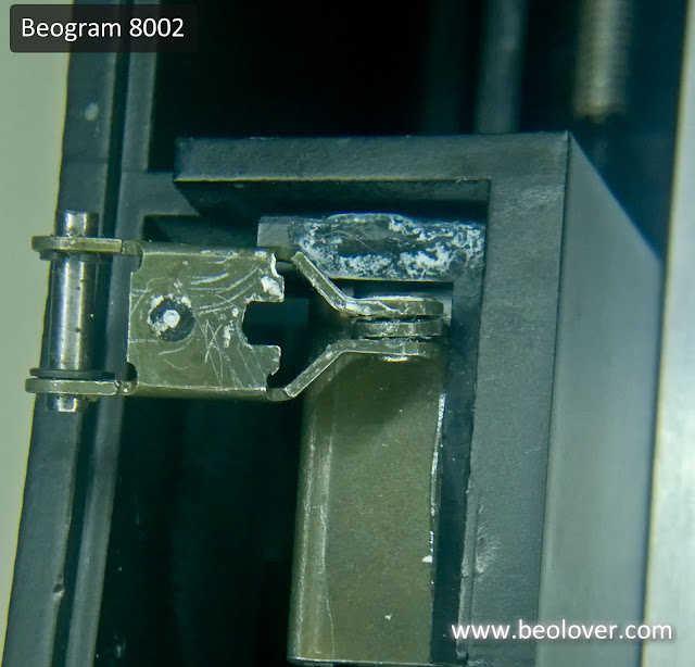
Last night I started on the lid assembly for this turntable so I could attach it today. I discovered that the black, metal base in the tonearm compartment had a problem. It turns out someone previously attempted to repair the underside where Bang & Olufsen also originally used double-sided tape.

The original tape deteriorates by now and can no longer hold pieces together. Instead of cleaning all of the old tape residue off another piece of tape was installed. It has now come loose.


No big deal. I just pulled the current tape off and used some Goo Gone to help get rid of the original tape residue.


I like to use 3M double-sided tape for this repair. I cut a few strips to customize the fit and reattached to the pieces.


Now I can focus on the dust cover hinge. Here is the original hinge for this Beogram.


It is missing the black plastic trim piece that hides the metal hinge from view. There was a bunch of dry, pasty grease residue so I had to clean all of that up and re-lubricate the hinge pivot.

Once I get into this part of the restoration I tend to not think about things like taking pictures so I forgot to get some detailed shots of this Beogram's hinge assembly. I do have pictures from one of my previous restorations of this hinge so I will use those to show what the dust cover hinge attachment is like.

Here is what a Beogram 8002 hinge assembly typically looks like when first opened up. The hinge clip that mounts to the lid was originally attached with some double-sided tape that eventually gives out. On this Beogram project I re-attached it with some epoxy. These pictures also show the hinge trim cover piece that this Beogram is missing.


The lid hinge and lid clip slide together to form the completed dust cover hinge.


The metal part of the hinge assembly is mounted on the leaf spring and there is an allen screw to adjust the amount of spring force to keep the lid raised. Note that you actually attach the hinge assembly to the leaf spring bar prior to attaching it to the lid clip.


For this Beogram project I was able to find a spare hinge assembly trim cover so the dust cover assembly looks much better now.


I also re-installed the owner's SMMC3 cartridge and adjusted the tracking force to the recommended 1.2 grams.


This turntable is ready for one last test play.


I decided to pull out an old Renaissance "Song For All Seasons" LP from 1978 and give it a spin.


Very nice 70's progressive rock sound. I believe this turntable restoration is complete.

Thursday, April 20, 2017

Beogram 8002: Taking the restored turntable for a spin

The last bit of repair on this Beogram 8002 is to fix the problems with the dust cover lid assembly. Meanwhile I started playing records on the Beogram as a test drive (or burn-in test). This is always the best part of the restoration.

I set up the Beogram 8002 in my office so I could listen to it play for the next couple of days. One of my kids is a trumpet player so I find myself listening to a lot of music by trumpet players. This picture is the Beogram playing Freddie Hubbard's First Light  LP. My copy has a very slight warp in it but the Beogram had no problems tracking it.


Once the listening tests are over and the dust cover assembly is re-attached this Beogram will be returning home.

Wednesday, April 19, 2017

Beogram 8002: Service Manual Adjustments

Going in to the Beogram 8002 service manual adjustments I already know that the fixed arm and tonearm horizontal parallelism needs adjusting. The tonearm appears higher than the fixed arm as you can see in this picture.


The tops of the two arms should be the same height and that height should be 19.5mm from the top of the Beogram platter. So the fixed arm needs to be adjusted up and the tonearm needs to be adjusted down.

To make all of the necessary adjustments I have to get to the underside of the tonearm carriage assembly. That means removing the rails and the tangential drive screw. I have to do this anyway to clean and re-apply some lubrication.

The red arrow in this picture shows the adjustment screw for the tops of the arms (the horizontal parallelism adjustment). The green arrow is for the vertical parallelism adjustment (the gap between the two arms). I am pointing that out as it turned out I needed to adjust it as well.


After adjusting the horizontal parallelism I got both arms to the 19.5mm height from the platter surface.


I installed a new tangential arm drive belt.


I also cleaned and checked the lubrication of the platter hub. The following pictures show the Beogram from platter hub removed to the sub-platter re-installed. I was able to find a spare tonearm assembly cover trim piece. The original one was missing from this turntable and the wires were exposed.


When I put the top platter back on and connected the main board the tonearm and platter worked okay but I noticed something was not right with the tonearm. When the Beogram 8002 tonearm is at rest you should be able to push the arm towards the fixed arm and have it spring right back to centered position when you let go. With this tonearm I was detecting an obstruction that was hindering the spring back action.

I was concerned at first because I couldn't see anything wrong. The vertical parallelism looked correct. I took a peek into the tangential arm tracking sensor assembly.

Note the spring clip in the picture below. That spring mechanism moves the tonearm back to a centered position when you move the tonearm away from the fixed arm.


Everything was fine in there. Nothing was scraping.

I finally realized the tonearm vertical parallelism adjustment screw was the problem. It had been adjusted incorrectly. While the gap between the fixed arm and tonearm looked fine, the tonearm raise/lowering bar was not operating correctly in the V-shaped channel of the brass adjustment screw.

The following picture of one of my own Beogram 8002 turntables shows the tonearm lift/lowering bar and the V-Channel adjustment screw. The lift bar has a spring mechanism that will attempt to keep the bar pressed down on the V-channel when the arm is in the raised position (not playing). If you manually move the tonearm towards the fixed arm the lift bar rides up one side of the V-channel. When you let go the tonearm should pivot back to a centered position as the spring loaded lift bar returns to the bottom of the V-channel.


On this Beogram 8002 project turntable the lift bar was getting slightly stuck at the top of the V-channel screw when the tonearm was moved towards the fixed arm. By re-adjusting the V-channel screw (which is the vertical parallelism adjustment screw) I was able to get the tonearm back to its normal, springy self.

The tonearm and fixed arms are also vertically parallel to each other.


I test played one complete side of a record and observed the linear tracking working correctly as the stylus remained always centered. I could see the tangential arm assembly motor adjusting the tonearm position pretty much ever half turn of the record. Very nice results after all of that disassembly/reassembly of the Beogram mechanics.

The last check I wanted to make was the voltage level of the light driven sensor in the control panel. This is for the Beogram forward/fast forward and reverse/fast reverse function. After the Beogram has been operating for at least five minutes the voltage of the forward/reverse sensor should be around 620mVDC in its normal state. This check is done my monitoring control panel connector P5-4 to P5-3 (ground) and P5-6 to P5-3 (ground). To adjust the sensor voltage levels there are two screws on the control panel that operate an aperture for the sensor lamp source as seen in the picture below.


The procedure requires checking the voltages at both test points a few times as each screw is adjusted. Each adjustment screw can affect the measurement at both test points. After a few iterations I got the sensor to a satisfactory level.

Tomorrow I will re-assembly the Beogram 8002 (except for the dust cover lids) and do some actual record playing testing.

Sunday, April 16, 2017

Beogram 8002: Recapping Complete

For the replacement of the electrolytic capacitors I will pick up where I left off...with the Beogram 8002 transformer box that I opened up. The 27uF capacitor for the motor circuit will be replaced using Beolover's nice 3D printed assembly. I like to measure the old capacitors to see how many are bad, out of tolerance or on the verge of being out of tolerance.

The original 4C1 27uF capacitor of this Beogram is out of tolerance by almost 20%. 


The replacement part just drops into the transformer box and the two leads soldered to the new 4C1 27uF capacitor. This is a bipolar capacitor so it doesn't matter which wires to connect to the capacitor module leads.


That is way better than soldering a new capacitor and letting it dangle loose inside the transformer box.

The next capacitor is the 2C28 47uF capacitor in the microcomputer case. I cleaned off the old thermal paste (that was starting to dry out) from the microcomputer integrated circuit and the heat sink. The 2C28 capacitor was replaced and new thermal paste was added to the heat sink. The replacement of the 2C28 capacitor is a little tricky as the negative side of the capacitor must be soldered to the board on both the trace side and the component side as noted by Beolover a while back.


For the Beogram 8002 main board I replaced all of the electrolytic capacitors 2.2uF and less with WIMA MKS capacitors (the rectangular, red capacitors in the picture). The rest were replaced with new 105°C, long lasting electrolytic capacitors. For the large 1C27 2200uF, 50V capacitor I like to use the three prong base off an original Beogram 1C27. I had a spare base so I used it here.


The center hole is for the capacitor positive lead. I take the capacitor negative lead and solder it to the metal base. After that I use black hot glue to secure the rest of the capacitor to the base and place it on the board. This makes for a solid installation of this capacitor like the original.


The last two capacitors are on the Beogram 8002 chassis - 0C1 and 0C2. These are easy to get to. Just remove three wires (the yellow, black and blue).


The next picture shows how close together traces are on the Beogram 8002 main board. When re-flowing the solder joints of the board connectors it is best to use a smaller tip on the soldering gun. If the tip is too wide it is really easy to accidentally create solder bridges between traces. I have to use a magnified lamp when soldering on this board to tell if the result is good.


That completes the electrical restoration of the Beogram. A quick check of the work with the Beogram turntable assembly verifies that everything is good.


Now it is on to the service manual adjustments which will make sure this Beogram is ready for full use again.

Thursday, April 13, 2017

Beogram 8002: Preparing the Restoration

The decision has been made to do the full restoration on this beautiful Beogram 8002. The first step is to open it up for service and prepare the parts for restoration.

These early eighties Bang & Olufsen audio components were designed to open up for servicing similar to an automobile hood. The modular design makes it nice to work on. There are still some tricks to learn in properly opening the units up and some out of the ordinary tools are a big help.

I already removed the dust cover and tonearm compartment lid assembly. I need to check why the alignment is off on that later so by removing it the lids won't accidently flip open and get damaged when the deck is tilted up.

To get the Beogram deck open there are only two screws underneath the left side that have to be removed. However, to open the deck up you must carefully detach the three suspension springs and when the deck lid is tilted up you have to maneuver the platter assembly to the right slightly. The reason for that is there is the deck cannot clear the tonearm assembly unless the platter assembly that holds it is shifted.

Here is the Beogram with the deck lid up (dust cover and tonearm compartment lid assembly already removed).


As noted in the photo, with the Beogram open I discovered another missing trim piece. There should be a black plastic cover for the exposed wiring board on the tangential arm assembly. I will look for a spare or fashion one out of a sheet of Dura-Lar.

Turntable adjustments and tests can be made with the Beogram opened up in this service position. For restoration work though I fully remove the Beogram assemblies so they can be worked on individually or connected together and tested.

This picture show the Beogram 8002 assemblies removed from the case and operating.


When I had first examined this Beogram I noticed the horizontal parallelism of the reference arm and tone arm was off. The tops of the two arms should be the same. In the picture below you can see the tone arm is slightly higher. The service manual has a procedure for adjusting that and it requires taking the tangential arm assembly out to get at the underside. That isn't a big deal as I was going to lift out the arm anyway to check the lubrication of the tangential arm drive.


Besides the service manual mechanical adjustment procedures this restoration will rework the Beogram 8002 main board. The electrolytic capacitors will be replaced and solder joints re-flowed on all of the board connectors. Here is the Beogram 8002 main board opened up.


...and inside the metal box with the microcomputer.


There is also a capacitor Bang & Olufsen engineers mounting in the transformer box. This capacitor is a coupling capacitor for the platter drive motor. It is obviously too big to have fit on the main board or on the platter chassis so it was put in the transformer box.


That is it for preparing everything for this restoration. It is time to start the work.