Featured Post

Beolover SyncDrive: DC Platter Motor Replacement for Beogram 4002 and 4004 (Type 551x and 552x)

Late Beogram 4002 and the 4004 (Types 551x and 552x), which have DC platter motors instead of the earlier synchronous AC motors usually suff...

Showing posts with label RSBG4000UK. Show all posts

Sunday, June 12, 2016

Beogram 4000: Increasing Tonearm Lowering Delay

After installing the new hood on the Beogram 4000 that I am finishing up I gave it some more playtime together with my Beomaster 6000 4-Channel (they just like each other...;-) and I realized that the arm lowered too fast. I first tried to increase the damper time constant by screwing the vale screw a bit further in, but to no avail. In fact the damper got very slow, but the needle still lowered very fast into the groove. What is going on!

I took the panels off again and had a close look. It turns out that the damper to tonearm linkage is very close to the damper plunger, and so it gets moved immediately when the damper starts moving. Since the damper needs to build up a bit of vacuum inside before it can do its damping action it is faster for the first mm or so and then becomes fully damped. This had the negative effect that the arm would be lowered already during this first mm before the damping action finally set in. 

I always wondered why later 4002/4004 models have a modified damper to arm linkage. This shows the modern version:
The setscrew on the lower end of the linkage allows the change of the distance between damper and linkage when the arm is up. The adjustment instructions in the 4002 manual yield a situation where there is a small gap between damper plunger and linkage, so that the damper does not rush into the linkage during its first mm of movement. This causes the arm to be lowered only after the motion is fully damped.

The Beogram 4000 on the other hand (and some older 4002 versions) have a linkage that cannot be adjusted:
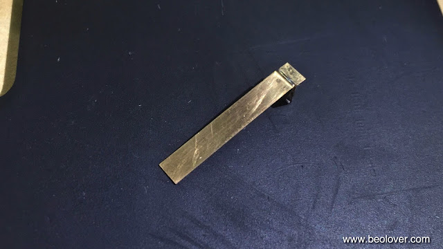
I scratched my head a bit how to introduce that gap a the damper plunger, and after a while it struck me that I could also alter the upper end of the linkage where it controls the lowering of the arm. I added a few layers of shrink tubing to the connecting end which lifted the linkage up a bit, creating the desired mm gap on the other end:
After this modification the arm lowered very smoothly.


Beogram 4000: Installation of a New Plexiglass Hood and Aluminum Trim

My current Beogram 4000 restoration is coming to a close. The final touch of the cosmetic work was to replace the original hood with a newly made reproduction hood provided by Classic Audio in Denmark. Classic Audio also provided a reproduced aluminum trim strip to be applied in the back of the hood. The installation of such a hood is straight forward: Here are a few impressions:

This shows the installation of the original hinge using new stainless M3 screws:

The machined holes in the new hood fit perfectly and the screws went in exactly like they would in an original hood. It is a good idea to protect the pristine plexiglass with a bag or similar while doing this procedure.
After the hinge was mounted, I applied the new aluminum strip. It came with adhesive backing, so all one needs to do is to remove the backing and then carefully apply the strip making sure that it is matching the edge of the plexiglass without making creases or folds. After some initial learning curve I finally had it on:
It is really amazing how clear such a new hood is. This simply cannot be matched by polishing a scratched original one:
Awesomely beautiful! I am very grateful that Classic Audio is providing this great service to the B&O community!
This is Beolove!


Thursday, June 2, 2016

Beogram 4000: New Aluminum Carriage Pulley

After electroplating all the spring terminals in the switches with gold, it was time to give this Beogram 4000 one more update: A new aluminum carriage pulley to replace the old wobbly plastic pulley. Here is an impression of the original pulley:
And here with one of Nick's beautiful aluminum pulleys!:
I would be happy to get you in touch with Nick if you would like to get a pulley for your own Beogram. They are also available for the 4002 and 4004 versions. This is Beolove!


Wednesday, June 1, 2016

Beogram 4000: Gold Plating of Terminals in Control System Switches

One of my customers expressed interest in acquiring a Beogram 4000 that I restored last year (this link will bring up most of my last year's posts on this Beogram 4000). One item left to do was to gold plate the contact terminals in the switches that determine the carriage position and the switches in the keypad. In my experience about 90% of all faults with the 4000 can be traced back to issues in these mechanical switches. They determine the states of the control system and the malfunction of just one of them can cause severe operational issues with the 4000. Hence, gold plating and straightening them out is a great idea if long-term stability is desired.

This operation requires to extract all contact terminals from the switches. This is a somewhat painful procedure since the terminals are inserted into the PCBs with spring loaded solder connections. Getting them out makes one wish that humans were outfitted with at least three arms and hands. But patience and skill can make up for that. So, let's go for it!:

This shows the keypad PCB removed from the keypad assembly:
The contact terminals appear black and oxidized. This shows them after removal:
And after electrochemical gold plating:
And yes, you counted correctly!: I forgot to take one out for these pictures...there are eight in total in the keypad...;-). Here is the final one:
Looks pretty bad, doesn't it?? After plating:
Much better, isn't it??

After straightening all of the terminals into their original shape I re-implanted them:
Very pretty! This is Beolove!

After this I put the keypad back together and tested it. To my frustration the reverse scanning function had trouble to activate fast scanning, indicating that the secondary on-position of the respective switch was not activated reliably. I had this issue before. There is a design issue with the switches in that the actuator is sometimes not long enough to allow the reliable activation of the fast scanning function. This mechanical issue can be alleviated by adding a bit of length to the actuator. I usually do this by putting a small dab of epoxy glue on the end of the actuator:
This solved the problem. 

On to the carriage position switches. These switches are responsible for activating arm lowering or end groove detection etc...This shows them in their original condition:
Probably the most black and oxidized terminals I saw so far. I removed them
polished them with some 2000 grit sand paper:
and then gold plated them:
After reinstalling a much different picture:
I replaced the PCB and tested the Beogram: Perfect function! All good now in the switches department!


Saturday, September 19, 2015

Beogram 4000: Polishing the Hood

Today I polished the hood of the Beogram 4000 that is on my bench right now (or rather sits next to my Beomaster 6000 4-Channel looking real pretty, even without the hood, playing Miles Davis' The Man with the Horn...;-). Not that I really enjoy the polishing of acrylic hoods, but the effort is definitely worthwhile...these decks just look so much better when the hood is nice and shiny. Usually they come in with significantly scratched hoods. This one was not different. Some deep ones - when one can feel them with a fingernail, one needs to start with 200 grit sand paper to even things out before starting to polish it back to new-like sheen. This one definitely was a candidate for the 200 grade:


And smaller scratches all over the surface.

This shows the hood after the 200 and then 400 grit:

And then during the Micromesh polishing steps:


This shows the end result after polishing with Micro-Gloss:

Pretty! Absolutely worth the multi-hour effort! There is no true Beolove without some degree of pain...;-)


Friday, September 18, 2015

Beogram 4000: Adjusting the Platter, Cleaning the Panels and Installing a 3D Printed Guiding Washer for the Cabinet

Today, I spent some time detailing the appearance of the Beogram 4000 that is on my bench right now. First I adjusted the platter height and position within the main aluminum panel. This is an important task, since only if the platter is centered and flush with the panels the Beogram looks right. When I got it the platter was way too low (and also so out of center that it was scraping on the panel):


So I adjusted the main bearing and the three suspensions of the chassis until things were right. Visit the original post for two videos that show in detail how to do that properly.

Here is a picture with everything adjusted and cleaned (the panels usually clean up very nicely with Mr. Clean Magic Eraser pads - just wet them a bit and then clean along the brush direction of the panels...):

How lovely! I can't wait until I'll have the hood restored!

While I played with these adjustments, I also rid this Beogram of the front center mounting screw of the plinth. This is a poor design, which they rectified in the later 4002 and 4004 models by installing an eccentric guiding washer instead of the floppy plastic washer and the shoulder bolt. 

Here is an impression of the original setup:

I recently designed a 3D printed replacement of the 4002-style washers, which is now available via the Beolover Shapeways Store. There is also a video about installing them. Here is a picture of the new washer in place:

I usually put a dab of Ballistol on the washers before installing them. That makes the plinth move in smoothly.


Wednesday, September 16, 2015

Beogram 4000: Installation of Hood Mounting Screw Springs

On the way to the perfect Beogram 4000 I realized that all 4000s that I so far encountered did not have the hood mounting screw springs that the later Beogram 4002 and 4004 have. These springs conveniently push up the screws making it really easy to take off and replace the hood of these turntables. I checked the service manuals, and indeed the Beogram 4000s do not have these springs included. I guess B&O practiced kaizen here and gradually improved their designs (even though I disagree with the change to DC motors and the implementation of the retro analog control system on the 4002/4 models - the 4000 is much more advanced in this department - I'd love to meet this designer for a chat if he is still around). Anyway, a Pilot G-2 07 pen donated a spring to the Beogram 4000 that I am currently restoring, which I cut in half and installed on the two bolts. I made a short video about the process. Enjoy:


On to doing the final adjustments of the platter height, and then there is the polishing of the scratched hood...this means a nice workout is coming up in Beolover's garage!

Monday, September 14, 2015

Beogram 4000: Zero Force Balancing and Tracking Force Calibration

The Beogram 4000 that I am restoring right now is getting ready for its first real test drive. Time to adjust the zero force balance and the setting of the correct tracking force. I made a video about this procedure a while ago on the occasion of a 4002 that crossed my bench. It is located here on my YouTube channel. The entire Beogram 4000 playlist can be accessed here

Here are a couple impressions from this particular Beogram 4000 restoration. The first step is zero force balancing. This requires the balancing of the arm with cartridge installed to a horizontal floating level when the force wheel is set to zero. I usually replace the locking washer of the original set-up with a M3 nut since the locking washer has too much play, which almost guarantees a change of the adjustment during the rigors of shipping. The nut holds the counterweight solidly in place:


Once the arm is balanced, the actual tracking force calibration can be undertaken. I do this with the original B&O tracking force balance. The force wheel is to be adjusted that the balance is horizontal after lowering the tip into the desired force spot on the balance:

Time to give this baby a spin!


Sunday, September 13, 2015

Beogram 4000: Installation of a Neutrik Gold Plated DIN5 Plug

Another standard upgrade that I do for Beogram 4000s is installing a new gold plated DIN5 plug. The original ones are not gold plated and tend to be a bit rusty after all these years. This Beogram 4000 was not different:

This shows it taken apart in contrast with the new shiny Neutrik plug (Newark 27B4483) insert:

After cutting the old plug off, I prepared the cable for the new plug. This is a good length for taking the outer insulation off:


It is a good idea to strengthen the signal leads a bit with solder after taking the insulation off. This makes it much easier to solder them nicely into the tabs of the pins. then it was time to solder the plug on:

And here the lovely sheen of new gold contacts:

This is golden beolove!


Saturday, September 12, 2015

Beogram 4000: Installation of a Grounding Switch That Allows to Connect System and Signal Grounds

The last Beogram 4000 that I restored had a strong hum while playing when I connected it to my Beomaster 6000 4-Channel phono input. This was fixed by simply connecting signal and system grounds. While I was not able to fully figure out why the hum occurred, I thought it wise to install a switch with which one can choose between the original grounding set-up with separate system and signal grounds (which typically results in a connection between them in the amplifier circuit) and a direct connection between the two right at the 4000 output. My original post about this procedure contains a detailed discussion of the electrical setup. I thought this to be a useful upgrade for any 4000 and so I decided to put a switch also into this one. Here are a couple pictures to document the installation of the switch on this Beogram 4000.

This picture shows the original setup. Signal and system grounds are connected separately to the shielded DIN cable. System ground is connected to the shield, while the signal ground is connected to the inner lead-shields:

Here is the set-up with the switch allowing the user to switch easily between the two setups. I also cleaned up the soldering mess of the as-found configuration:


A discussion of the grounding strategies of the later Beogram 4002 and 4004 models is included in this video (they actually went from the original separate grounds model to connecting them in the 4004, i.e. my switch simply implements both strategies in one set-up allowing a choice between them):

Friday, September 11, 2015

Beogram 4000: Adjusting the Gap at the Carriage Servo Pulley Bearing

When I tried out the carriage mechanism of the Beogram 4000 that I am restoring right now after repairing and adjusting the tracking mechanism, I found that the threaded rod that advances the carriage had a lot of longitudinal play. Here is a picture of the setup:


The play manifested itself in an unwanted 'clacking' every time the carriage changed its direction. This turned out to be an easy fix. All I had to do was to remove the servo pulley and remove the damaged locking ring and the worn out plastic washer:

This is the pulley. It is held in place by a setscrew whose threads are in the small brass plate that is inserted into the slot above the shaft receptacle. It should be noted that it usually sits very tightly on the shaft and that it took some careful 'convincing' with a flat head screwdriver to pry it off the shaft.


I replaced the locking ring and the washer by a thick 2-56 nylon washer which fit perfectly on the shaft. The locking ring is not needed since the pulley is locked in place with the set screw:

I also lubricated the shaft in its bearing and the nylon washer with a bit of silicone grease.
Then I put the pulley back on:
Now it has only a fraction of a mm play and the carriage moves very precisely and without strange noises. I added a bit of silicone grease to the threaded section of the shaft and that quieted the mechanism further.