Featured Post

Beolover SyncDrive: DC Platter Motor Replacement for Beogram 4002 and 4004 (Type 551x and 552x)

Late Beogram 4002 and the 4004 (Types 551x and 552x), which have DC platter motors instead of the earlier synchronous AC motors usually suff...

Showing posts with label system. Show all posts

Thursday, May 25, 2017

Beogram 4004 (5526): Restoration of the DC Platter Motor and RPM Stability Test

After replacing the RPM trimmers, the RPM relay and the light bulbs in the RPM trimmer panel with LEDs, it was finally time to restore the DC platter motor of this Beogram 4004 (5526). This sequence is important, since one can only test the RPM stability performance of the motor properly after the entire RPM control circuit has been rebuilt. This shows the extracted motor:
The motor needs to be completely disassembled to get to the dried out Oilite bearings:
The bearings are the two small donuts on the black pad. I infused them with motor oil under vacuum:
The raising bubbles indicate that air is drawn from the porous brass bearing material. This creates space for oil to enter the bearing. After about 12-24 hours the process usually stops, at which point the bearings are again full of oil.
This shows the bearings after the infusion process:
After reassembling the motor I put it back into the deck and adjusted the RPM with the BeoloverRPM device:
Then I used the device to measure a RPM stability curve over 18 hours:
This motor showed an exceptionally stable RPM performance and can be considered ready for duty.


Monday, April 25, 2016

Beogram 4002 (5514): RPM Performance Measurement after Restoration of DC Motor and Control System

After rebuilding the DC motor and the control system of the Beogram 4002 (5514) that I am restoring right now, it was time to do a RPM performance test. I set up my BeoloverRPM device that allows the long-term logging of the platter RPM, and then did a 24 hrs test:

After the data was logged on my computer, I graphed it relative to a measurement that I took when I initially received the unit for restoration. This shows the two curves in comparison:
The red curve shows the performance before the restoration. The typical telltale sudden negative RPM spikes are visible that indicate failing brass sleeve bearings in the DC motor. This is very common for DC motor Beograms. In this case the spikes are still fairly moderate, but would have been audible since they are in the 1% range. The black curve shows the performance after rebuilding the motor and the installation of new RPM trimmers and RPM relay. The large spikes are gone and the variations are much smaller. There are still some variations, which are related to the intrinsically slightly erratic performance of the analog motor control system, which is affected by temperature changes and probably the moon phase (that was a joke...;-). Some Beograms show them others do not. At this point I do not have an answer why they sometimes occur. The good news is that they are fairly slow over time and also small enough that one cannot hear them. The short term 'wow and flutter' RPM changes (the high frequency 'noise' on these curves) are within the spec given in the service manual (0.05%).  So this Beogram is back in business.

Sunday, February 7, 2016

Beogram 4002 (5513): More RPM Measurements

This is a follow up on yesterday's post about this Beogram 4002 (5513). I did an overnight RPM performance measurement with my BeoloverRPM device. This is the curve that I measured:
This result is pretty much as good as it gets for the DC motor versions. Minimal <0.05% variations over time satisfying the specifications stated in the service manual. The initial slope during the first couple hours is usually observed in the 551x and 552x models. I currently think it is a result of D13 (the Zener diode that stabilizes the DC motor supply) and R12 with which it forms a pretty stiff (i.e. high current) voltage divider to set the base voltage of TR2 heating up. After a while the temperature stabilizes at a certain value in equilibrium with the environment. The band gap change in the semiconductor of the Zener changes its Zener voltage and with that the motor slowly gets a bit more power until a sable condition is achieved. This 'ancient' voltage regulator design is a bit of a drawback of the DC motor versions of the 4002. But one should not get to worked up about it since the change is pretty slow, and only represents a total ~0.3% change, hardly noticeable by most listeners. I am thinking this phenomenon could possibly be alleviated via the adaption of the circuit to use a modern voltage regulator. 

Beogram 4002 (5513): Initial RPM Performance Characterization

This is a follow up to my initial post about this Beogram 4002 (5513). In the meantime I did a RPM performance evaluation of the unit using my recently developed BeoloverRPM device.

This measurement clearly demonstrated the suspected sudden speed variations. This graph shows the RPM vs. time over an approximate 24 hrs period:
The sudden negative spikes suggest that the DC motor control system and the motor itself needs an overhaul.


Monday, December 7, 2015

Beogram 4000: Adjusting the Tracking Force and Replacing the Strange Original Front Center Cabinet Guiding Washer

The Beogram 4000 that I just finished up is now running smoothly. I am playing 'Song for My Father' by Horace Silver (unfortunately a reissue, since the original first pressings are unaffordable these days...sigh!!), which is one of my favorite jazz tunes while writing this post.
Before I got here, however, I still had to do a bit of work on this Beogram: Adjusting the tone arm weight and limits. I also replace the strange standard guiding washer that is typically found installed in the front center guiding slot to ensure a straight movement of the plinth when it is pushed back to secure the aluminum panels. Here is a picture of the original washer including the shoulder bolt:


This awkward setup just does not work well, and consequently later Beogram 400x have a much better design based on an eccentric washer shape. I recently designed 3D printed replicas of this design since they often crack in 4002 and 4004 models that are outfitted with plastic versions of it. See this video for their installation. The parts are available via my Shapeways store (five washers are needed to replace all of them).

Here is a picture of the new washer installed together with a new M3 bolt (note the much lower profile of the assembly, which is beneficial when installing the aluminum panels as chafing is avoided):


After this small detail, I did the arm adjustment. Most important are the zero weight and tracking force calibration and the proper adjustment of the arm lowering limit, which can be the final stop gap that keeps the platter from ripping the needle out of the MMC cartridge in case of a failing photosensor or misadjusted sensor bulb. Earlier I posted videos about these two procedures (tracking force calibration, arm lowering limit). Equally important is the improvement of the weight adjustment screw assembly, which I usually upgrade with a M3 nut and washer. This allows to permanently fix the adjustment in place, which is critical for a successful out-of-the-box setup when I send the turntable back to Italy. The original setup with the locking washer is too flimsy, which can result in a change of the calibration during shipment. Here is a picture of the installed nut:

And here the needle on the tracking force gauge at 1g after adjusting everything:

Ah...Horace Silver via a perfectly adjusted 4000 and my Beomaster 6000 4-Channel - perfect pairings!...I am in Beoheaven..;-)


Monday, November 30, 2015

Beogram 4000: Installation of a New Gold Coated DIN5 Plug and a Grounding Switch

The beautification of the Beogram 4000 that I am restoring right now continues. I installed a grounding switch and a new gold plated Neutrik DIN5 plug. The grounding switch allows to combine signal and system grounds of the Beogram. This essentially allows to switch between the grounding scheme of the later 4004 models and the 4000/4002 set-up where system and signal ground are separated. Depending on the amplifier set-up it can be beneficial to be able to select either one to avoid the formation of ground loops that can cause humming. I recently made a post that illuminates this in more detail.

This shows the switch installed. The shown orientation corresponds to the original 4000 set-up with separated grounds. Flipping it to the left would connect both grounds:


Here are a few pictures of the DIN5 replacement. This shows the corroded original plug:


And here is a picture of the new plug:

Beautiful! this shows the leads as connected on the inside:

Good to know that the precious MMC signals can now travel unimpeded!


Sunday, November 8, 2015

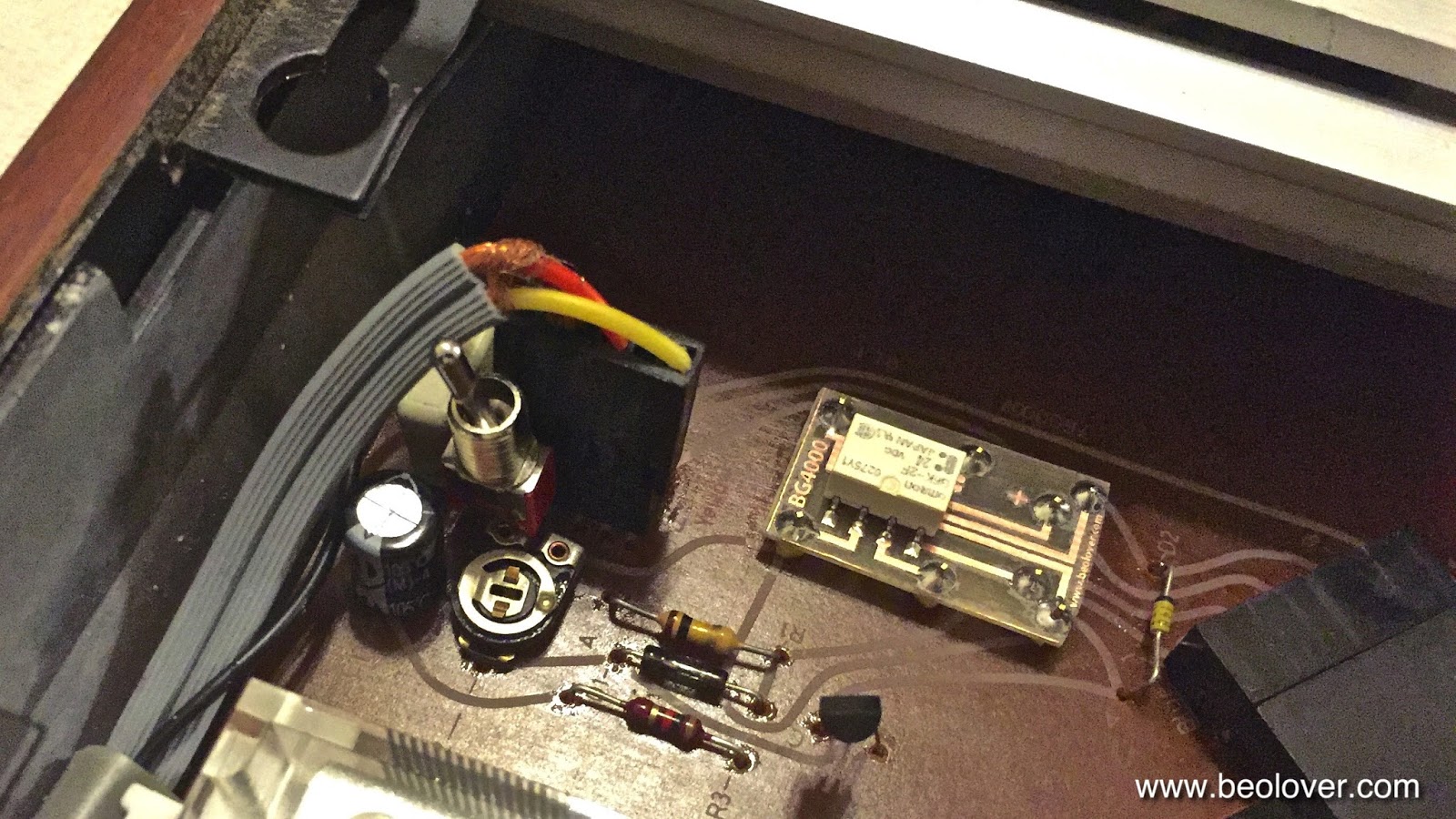
Beogram 4002 (5513): Installation of a New Output Relay and a GND Switch

While I was testing the Beogram 4002 (5513) that I restored in recent weeks I realized that the output relay once in a while would not open up after the tip touched down, hence, preventing the audio signal from reaching the amplifier. Luckily the relay is the same type that is used for RPM switching in both 4002 and 4000 models. Therefore, I was able to use the breakout board that I recently developed for replacing the RPM relay in a Beogram 4000 with a modern encapsulated SMD signal relay.

While I installed the new relay I took the opportunity to also install a switch on this board that allows to tie signal and system grounds to deal with humming problems if necessary. Depending how the amplifier is setup it can become advantageous to tie the two grounds together to prevent the formation of grounding loops and/or open leads that can introduce ambient EMI into the sensitive phono preamp input. 

This shows the original relay:

And after installing the SMD replacement and the switch: 

This shows the board after installing it in the Beogram and replacing the plug that connects the cable:


Saturday, September 12, 2015

Beogram 4000: Installation of a Grounding Switch That Allows to Connect System and Signal Grounds

The last Beogram 4000 that I restored had a strong hum while playing when I connected it to my Beomaster 6000 4-Channel phono input. This was fixed by simply connecting signal and system grounds. While I was not able to fully figure out why the hum occurred, I thought it wise to install a switch with which one can choose between the original grounding set-up with separate system and signal grounds (which typically results in a connection between them in the amplifier circuit) and a direct connection between the two right at the 4000 output. My original post about this procedure contains a detailed discussion of the electrical setup. I thought this to be a useful upgrade for any 4000 and so I decided to put a switch also into this one. Here are a couple pictures to document the installation of the switch on this Beogram 4000.

This picture shows the original setup. Signal and system grounds are connected separately to the shielded DIN cable. System ground is connected to the shield, while the signal ground is connected to the inner lead-shields:

Here is the set-up with the switch allowing the user to switch easily between the two setups. I also cleaned up the soldering mess of the as-found configuration:


A discussion of the grounding strategies of the later Beogram 4002 and 4004 models is included in this video (they actually went from the original separate grounds model to connecting them in the 4004, i.e. my switch simply implements both strategies in one set-up allowing a choice between them):