Featured Post

Beolover SyncDrive: DC Platter Motor Replacement for Beogram 4002 and 4004 (Type 551x and 552x)

Late Beogram 4002 and the 4004 (Types 551x and 552x), which have DC platter motors instead of the earlier synchronous AC motors usually suff...

Showing posts with label rebuilding. Show all posts

Saturday, November 17, 2018

Canada Beomaster 8000: Rebuilding the displays

I have the new smd LED components installed in the Beomaster 8000 segmented display boards and I am running a burn-in test on them.

It is a little difficult to capture (in a photo) what the rebuilt displays look like without the top lens cover on but the purpose of this test is to make sure all of the segments work. I usually run this burn-in test for twenty-four hours. That gives the new components a decent amount of time to fail if they are going to. I would hate to bundle everything up then have to disassemble the displays again.


To get to this point I removed the display modules from the Beomaster 8000 display board.


There are white and red tabs on the rear of the display board modules that hold the light guide and lens cover in place. Those tabs were originally part of the plastic sub-assemblies and melted down to secure the full display assembly. Since those cannot be removed and reused I have to just cut them off and use a different way to re-assemble the display modules after I rebuild them.

Here is the channel balance display board with the light guide and lens cover removed.


You can see these Bang & Olufsen display modules were very custom and the tiny, smd-like LED components cannot be replaced. We could locate the LEDs that have failed and just change those. However, that would result in a noticeable difference in the red illumination because the new smd LEDs are not exactly the same as the originals. They are very close but not the same. So it is best to change all of them. Another equally good reason to change all of the LEDs is because you can bet that if you only changed the failed LEDs the remaining good ones will likely fail as well. It's definitely better to get everything done while the Beomaster is open.

Here are some pictures from previous Beomaster 8000 display repairs that I use as a reference for this task.

This first picture shows the new smd LED component next to the original B&O LED.


This picture shows identifier markings on the replacement smd LED component for reference.


The next step in the display rebuild after removing the light guide and lens cover is to cut out the original LED component.


I gathered a number of my Bang & Olufsen display modules that I have been wanting to rebuild and hope I can take the opportunity, while I am display repair mode, to get them done as well.

To prepare each display board for the new smd LED components I cut off the small solder pad that the original LED cathode rested on. That makes the gap between the anode and cathode pads better for the new components.


It is important to "tin" the solder pads before mounting the smd LED components. That will ensure a good, reliable connection.


Now for the actual mounting of the new smd LED components.

I have to say that this task is one of the most time consuming restoration tasks and requires a lot of patience to handle the smd LED devices while soldering them in place. The technique I use (and recommend) is to mount the smd LED components just on one lead. The reason is because the LED component must fit just right in the plastic light guide of the display module. There are always several LED components that I have to reposition slightly to correctly function inside the light guide. That also means the soldering process is to first position the smd LED with tweezers, solder one side to secure it, check the fit with the light guide, reposition if necessary and finally, solder in the other side. Quite labor intensive and hard on the eyes.

Here is a fit check of the smd LED in the light guide.


Once all of the new LED components have been fit checked I finish soldering the LEDs to the board.


Here is the completed FM tuner frequency display board.


On to the remaining three modules.

Another tip is to have a reference picture or (even better) a spare display board to use as a reference when mounting the new LED components. This task is very tedious so be disciplined to check the polarity carefully with each LED mounting.  It is also another good reason to only solder one side initially.


Here is the completed LED replacement on the Beomaster 8000 selected source display board.
Note: The glare from my lighting off the no-clean flux residue makes a couple of the solder connects appear shorted.


The volume level display board is next.


Finally the channel balance display board. This board is the easiest to position the smd LED components on because it doesn't have pads where the LED mounts. However, the narrow trace makes soldering in the LED components a little tricky and this board is usually the one to have a connection problem.


Once the twenty-four hour burn-in test is complete I can reassemble the four display components and wrap up the display board. Then it will on to functional testing with this Beomaster.

Tuesday, August 28, 2018

Texas Beomaster 8000: Output amplifier boards rebuilt

The two output amplifier boards for the Beomaster 8000 from Texas are now rebuilt. That gives me two sets of Beomaster 8000 amplifier boards to bench test.

These two (left and right) output amplifier boards are more typical of what I find on a Beomaster 8000 restoration. There are some very distinct darkened areas on the component side of the board caused by heat coming off the board components.

I started with the right channel board. No particular reason as both boards are identical.


I like to be methodical and work one board at a time and one side of the heatsink mounted components at a time. That is safer in preventing mistakes as I have the other output amplifier assembly to refer to.

Here is the heatsink with the PNP Darlington transistors removed.


It looks nice and clean but the job never gets any easier regarding the messy old thermal paste cleanup.

I installed the right side (PNP Darlingtons - 5IC204, 5IC205, 5IC206) on their Sil-pads and then worked the left side (NPN side - 5IC201, 5IC202, 5IC203).


There is one small place I still use some thermal paste and that is where the PTC resistor fits on the heatsink.


Although the right side of the heatsink assembly mounts the three PNP Darlingtons (5IC204, 5IC205, 5IC206) it does have one NPN transistor (5TR208 - BD135).


Now for the output amplifier board.  I replaced the six electrolytic capacitors and two trimmer resistors. I also took the opportunity to clean all of the old dust and grime off the board so it looks as close to new as I can get it.

Before


After


While the wires from the heatsink components were disconnected from the output amplifier board I measured the transistors to verify they were still good.  The transistors measured good and I reconnected the wires.  As for the electrolytic capacitors, this right channel board had several that were completely shot and the others were out of tolerance.


On to the left channel output amplifier board.

Like the right channel it had quite a bit of grime and dust.


The heatsink mounted transistors all checked out and the electrolytic capacitors still had capacitance...but almost all of them were out of tolerance.

Here is the cleaned up board with its new components.


I saved the messy heatsink mounted component task for last on this one.

Here is the right side cleaned and prepared.


...and here are the left and right channel boards completed and ready to be tested.


Tuesday, December 29, 2015

Beogram 4000: A New Pulley, Hood Bumpers and Shipping Back to Italy

The Beolover always strives to improve his craft and get things as perfect as possible. So I realized that I was not fully done yet with the restoration of the Beogram 4000 from Italy. My recent efforts to restore a Beogram 8000 from Japan introduced me to the concept of rubber hood bumpers that soften the impact if the hood is closed. It makes quite a big difference in terms of how it feels to close the hood. The sound when the hood seats on the enclosure is just so much more solid when the bumpers are present. Unfortunately they all seem gone at this point in time, and that is the reason that it took me some time to realize that all the classic B&O decks actually have(had) them! All that is usually left are some small holes filled with black degraded rubber remnant. This shows how it looked on the hood of the Beogram 4000:
It is easy to get the black stuff out with a 2 mm drill bit operated by hand (do NOT put it on a Dremel or similar...it is easy to damage the plexiglass):
Like with the Beogram 8000, rubber O-ring segments work well to restore the bumpers. In the case of this 4000, however, I needed to use 2mm diameter metric ones since the 0.1" type I used on the Beogram was too thick to squeeze into the holes. I glued the segments in with a bit of contact glue on the tip of the segment. Then I used my 3D printed cutoff template that I developed for the Beogram 8000 and razorblades the excess length off:
A perfect-length bumper resulted:
It has the right length to right the hood into a horizontal alignment with the plinth. The way the hinges are designed at the back of the hood, a ~1mm gap should be around the entire perimeter between hood and plinth if the hood is to be perfectly horizontal. These bumpers guarantee that. Beautiful!

Beyond this issue I also was a bit annoyed that the carriage ran a bit noisily when returning to the home position after a record was played to the end or OFF pressed. This was the result of a somewhat wobbly pulley, a result of a crack in its set screw assembly:

I exchanged it with a custom manufactured Aluminum pulley provided by Nick (via www.beoworld.org):
This fixed the issue and also looks beautiful. I think I will make this a standard part of my restorations since most pulleys are (or will be soon) cracked and/or run wobbly. This pulley quieted the mechanism down quite a bit and made it much more pleasant to use this Beogram 4000!

After these two tasks it was finally time to send it off. My customer requested state-of-the-art Beolover double boxing, and so I used this occasion to make a short video about the proccess:


May the Force (and gentle FedEx men&women) be with you on your way to Italy!


Tuesday, December 22, 2015

Beogram 4000: End Groove Detection Issue

After polishing the hood I thought I was done with this Beogram 4000, but not so. A last full performance check before boxing it up revealed a strange fault when ON was pressed with no record on the platter. The carriage would properly travel inwards in search of a record, but then before hitting the end switch ES the carriage would suddenly stop. Only pressing FF would release it from this state. However, then after letting the FF key go the carriage would immediately travel back without even touching the ES. In a healthy state the carriage should travel until the ES is activated and then it should return to the home position.
A closer look revealed that the carriage stopped right when it closed the MV switch that enables the end groove detection mechanism. Here is the relevant section of the circuit diagram:

Here is how it works: Whenever the MV switch is activated by the slide, MV' and MV are connected in the diagram. This puts part of the voltage on the motor across BE of TR24. So whenever the motor revs a bit higher, such as when the needle enters the end groove, the transistors 24/23/22 are activated and DS finally goes LOW. This tells the control system that it is time to lift the arm and drive the carriage home. Now this mechanism is of course only useful when the needle is on the record and entering the end groove. When the arm is up and the carriage is driven forward or backward this mechanism needs to be disabled. This is achieved via D4 which feeds the collector of TR25 into the base of TR23. 
The collector can only be high if FF is activated either by pressing the key or via Q0' which is LOW whenever the carriage is driven towards the center of the record after pressing ON. The tracking mechanism does not use TR25 since it directly goes into TR27/28, i.e. end groove detection is not disabled if the carriage tracks normally.

Further tests of the matter revealed that Q0' remained LOW even as the carriage stopped. This told me that the control system was still of the opinion that the carriage should move, hence the fault needed to be on the executive side of the system, i.e. right here in the MV circuit. I measured D4 from the back of the installed main PCB and promptly saw that it was open circuit, which killed the deactivation mechanism, and the end groove detection mechanism was active even with the arm up. After turing the board around I saw that the diode was cracked in half:

The original OA90 diode is a Germanium diode, but can easily be replaced with a modern 1N4148 Si signal diode since its only function is to block any voltage from the MV circuit to apply to the collector of TR25. Here is a picture of the 4148 installed:

After this I replaced the board and gave the deck a test drive. All good again. Listening to Walt Dickerson's "To My Queen" while I write this, which is definitely one of my all time jazz favorites. O.k. maybe now it is time to finally send this 4000 back to its owner.


Sunday, December 13, 2015

Beogram 4000: Polishing the Hood and a Strange Hinge Pin

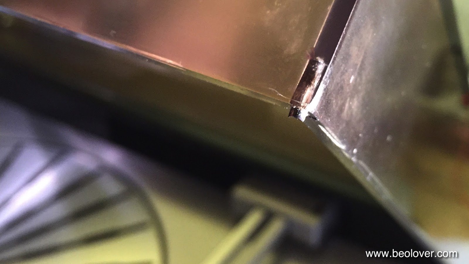
I am giving the Beogram 4000 that I restored recently the final touches. The last item to check off on the list is always polishing the hood. Like most Beograms that I saw so far this one also had a badly scratched up hood from carelessly stapling things on top of it while it sat in 'storage'. This unit had a couple more items that needed to be taken car of: One of the hinge pins was not original. At some point the short press-fit pin must have 'vanished' (one really wonders why someone would take it out...but such is the human creativity...;-), and a replacement pin was installed. The 4 mm replacement pin fit well into the hinge parts, but was too long and so it stuck out a bit:

Here a picture from the bottom of the hinge assembly:
I took the pin out and cut it by 4 mm with a jig saw and a metal blade. That allowed the pin to be inserted a bit deeper and it looks original now:
On the other side of the hood the aluminum trim had come off from the plexiglass:

I fixed that by applying a strip of double sided tape and pressing the strip back to the hood body. I recommend to not use epoxy or similar glue for this since the aluminum strip covers the screws that hold the hood to the hinge, and if the hood ever needs to be take off the trim needs to be pried off.

Anyway, after these tasks I set out to polish the hood. this one was special since it also had some issues on the inside, which is much more difficult to fix since it is hard to polish the inside. Luckily the damage was fairly small and most of it appears to have been tape residue:

I was able to remove it with a bit of detergent and a Mr. Clean Magic Eraser Pad. After that it needed a bit of buffing with polishing fluid, and that seems to have done the trick. There are a few more small very localized dings on the inside, but I chose to let them be since it is almost impossible to to a full sanding/polishing job on the inside since one cannot get to the corners.

Then I focused on the main job, the outside of the hood. Here are a couple impressions of the degree of scratching:


Nothing too special, but the depth of the damages required to start out with 200 grit sand paper to level the surface with the deepest damages:

This was followed with 320 grit:
and 400 grit, the first wet-sanding step:

It starts getting clearer already, but a full treatment with Micro-Mesh is required to get back to a fully translucent state:


And finally after buffing it with polishing fluid:

all good in the hood department now! A few more days of testing and this Beogram 4000 is ready for its journey back to Italy!