The two output amplifier boards for the Beomaster 8000 from Texas are now rebuilt. That gives me two sets of Beomaster 8000 amplifier boards to bench test.
These two (left and right) output amplifier boards are more typical of what I find on a Beomaster 8000 restoration. There are some very distinct darkened areas on the component side of the board caused by heat coming off the board components.
I started with the right channel board. No particular reason as both boards are identical.
I like to be methodical and work one board at a time and one side of the heatsink mounted components at a time. That is safer in preventing mistakes as I have the other output amplifier assembly to refer to.
Here is the heatsink with the PNP Darlington transistors removed.
It looks nice and clean but the job never gets any easier regarding the messy old thermal paste cleanup.
I installed the right side (PNP Darlingtons - 5IC204, 5IC205, 5IC206) on their Sil-pads and then worked the left side (NPN side - 5IC201, 5IC202, 5IC203).
There is one small place I still use some thermal paste and that is where the PTC resistor fits on the heatsink.
Although the right side of the heatsink assembly mounts the three PNP Darlingtons (5IC204, 5IC205, 5IC206) it does have one NPN transistor (5TR208 - BD135).
Now for the output amplifier board. I replaced the six electrolytic capacitors and two trimmer resistors. I also took the opportunity to clean all of the old dust and grime off the board so it looks as close to new as I can get it.
Before
After
While the wires from the heatsink components were disconnected from the output amplifier board I measured the transistors to verify they were still good. The transistors measured good and I reconnected the wires. As for the electrolytic capacitors, this right channel board had several that were completely shot and the others were out of tolerance.
On to the left channel output amplifier board.
Like the right channel it had quite a bit of grime and dust.
The heatsink mounted transistors all checked out and the electrolytic capacitors still had capacitance...but almost all of them were out of tolerance.
Here is the cleaned up board with its new components.
I saved the messy heatsink mounted component task for last on this one.
Here is the right side cleaned and prepared.
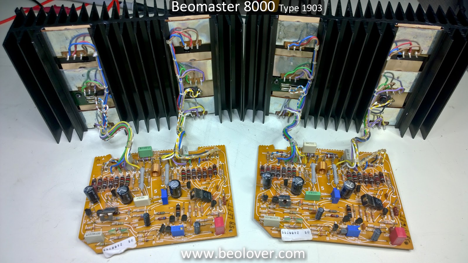
...and here are the left and right channel boards completed and ready to be tested.
Featured Post
Beolover SyncDrive: DC Platter Motor Replacement for Beogram 4002 and 4004 (Type 551x and 552x)
Late Beogram 4002 and the 4004 (Types 551x and 552x), which have DC platter motors instead of the earlier synchronous AC motors usually suff...
Showing posts with label thermal insulator. Show all posts
Tuesday, August 28, 2018
Monday, March 26, 2018
Beomaster 8000: Power Supply PCB Recap
Besides the +5 V, ±15V power transformer there were some rust spots on the bottom plate of the Beomaster cabinet.
I used a rust neutralizer on the bad areas of the transformer first. After that dried I used flat black rust preventative paint. Here is the cleaned up cabinet compartment where the +5V, ±15V transformer and power supply board go.
On the power supply board recap I cleaned dust and debris from the board and replaced the electrolytic and tantalum capacitors. This power supply board must have been worked on in the past. A few of the capacitors do not look like original capacitors what would have come from the Bang & Olufsen factory. The large +5V, ±15V reservoir capacitors are not fixed to the board with double-sided tape like most of these boards.
I always like to measure the capacitors I remove just to see what condition they are in. Most of the capacitors are within tolerance but there are always quite a few that are borderline to way out of tolerance.
Here is a good example of failed capacitors from the power supply board. One of the 10uF, 63V electrolytic capacitors measures 39uF now! A little off I would say ;-).
Failing the opposite direction this 22uF capacitor is only 11uF now.
The ESR values are also quite high on those two capacitors.
On capacitors that are still in tolerance we always change those to new capacitors as well. They have lived longer than expected but time is not on their side. With the Beomaster opened up it is best to replace them now and be assured they won't fail for another forty (or more) years.
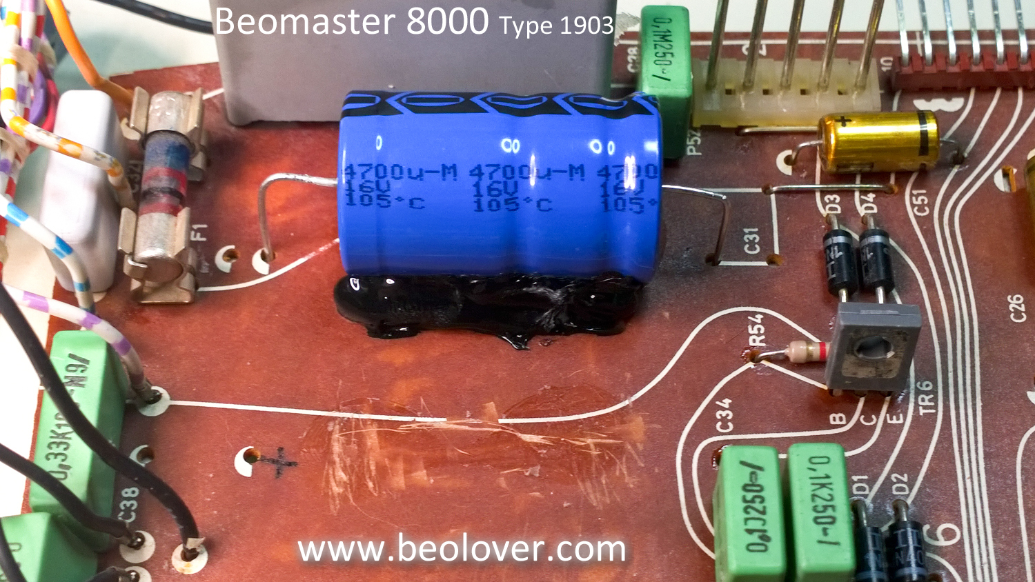
When replacing the +5V, ±15V reservoir capacitors I run a bead of hot glue along the bottom to secure the capacitors to the PCB so that won't move. The hot glue dries right away and can easily be removed if necessary.
Here is the power supply board with all of the capacitors replaced and new thermal insulators on the +5V, ±15V regulators. The metal shield around the remote control circuit is kind of a pain to remove and reinstall but that housed the failed 22uF capacitor so it is a necessary step.
With the cabinet and transformer cleaned up the parts are reinstalled.
It's starting to look like new again.
Monday, January 22, 2018
Beomaster 8000: Left & Right Channel Output Amp Boards
The actual component replacement on the left and right channel output boards (identical boards) is pretty simple. Just six capacitors and two trimmer resistors. Most of the work is dealing with the messy thermal compound on the heatsinks.
The original mica insulators and thermal paste work very well. However, due to the removal and reinstallation of these assemblies being so messy I have been switching to sil-pad thermal insulators. They are very easy to use and do not require the messy thermal paste...which seems to get on everything.
Here are the two boards with the components removed from the left channel board. While the components are removed I clean off the old dust that has accumulated over the years.
Here are the recapped boards.
The original trimmer resistors for (no-load) idle current and DC offset are replaced with multi-turn, sealed trimmer resistors.
For this application I have started to use sil-pad sheets instead of precut pads for the transistors. The sheets can be cut to cover a larger area which is what I like to do on these heatsinks because the mounting of the transistors can result in the shifting of components.
Installation of the transistors on the heatsinks is done by starting at the bottom and working to the top. The metal spring clips that hold the transistors in place have to slide over the top side of the transistor. The transistors shift a lot during this process and the spring clips are a little tricky to get into place. You can imagine the mess to clean up when thermal paste is used.
Here are the completed boards.
The next step is to perform the initial no-load, idle current adjustment on these two boards. These output amplifier boards can be powered and adjusted outside the Beomaster if you have the proper bench power supplies.
The original mica insulators and thermal paste work very well. However, due to the removal and reinstallation of these assemblies being so messy I have been switching to sil-pad thermal insulators. They are very easy to use and do not require the messy thermal paste...which seems to get on everything.
Here are the two boards with the components removed from the left channel board. While the components are removed I clean off the old dust that has accumulated over the years.
Here are the recapped boards.
The original trimmer resistors for (no-load) idle current and DC offset are replaced with multi-turn, sealed trimmer resistors.
For this application I have started to use sil-pad sheets instead of precut pads for the transistors. The sheets can be cut to cover a larger area which is what I like to do on these heatsinks because the mounting of the transistors can result in the shifting of components.
Installation of the transistors on the heatsinks is done by starting at the bottom and working to the top. The metal spring clips that hold the transistors in place have to slide over the top side of the transistor. The transistors shift a lot during this process and the spring clips are a little tricky to get into place. You can imagine the mess to clean up when thermal paste is used.
Here are the completed boards.
The next step is to perform the initial no-load, idle current adjustment on these two boards. These output amplifier boards can be powered and adjusted outside the Beomaster if you have the proper bench power supplies.
Wednesday, January 17, 2018
Beomaster 8000: Power Supply Board Recapping
The Beomaster 8000 Power Supply board restoration consists of changing out several electrolytic capacitors along with a couple of tantalum capacitors with new 105°C capacitors. As I normally do I use WIMA MKS capacitors where the capacitor value is less than 10uF.
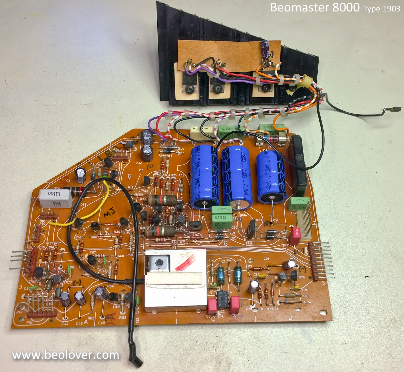
Here is the before picture of the power supply board.
The capacitor replacement is pretty straight forward with the exception of one capacitor located inside the metal shield box on the board and the three large, axial capacitors (2200uF and 4700uF) that require some glue to secure.
There is also a separate heat sink assembly for three voltage regulators. I started with that assembly and replaced the lone 10uF capacitor. While I did that I decided to clean off the old thermal grease and change out the thermal insulators.
On the three, large axial capacitors I scraped off the old mounting glue to prepare for the new capacitors.
For this type of application a hot glue gun works great as the glue works fast and can always be removed in the future if necessary.
The metal shield box for the Beomaster remote control receiver is not too bad to remove but does require de-soldering four mounting tabs. Here is the box removed and the power supply board recapped.
The shield box is soldered back in place, the board connector solder joints are reflowed and this board is done.
Here is the before picture of the power supply board.
The capacitor replacement is pretty straight forward with the exception of one capacitor located inside the metal shield box on the board and the three large, axial capacitors (2200uF and 4700uF) that require some glue to secure.
There is also a separate heat sink assembly for three voltage regulators. I started with that assembly and replaced the lone 10uF capacitor. While I did that I decided to clean off the old thermal grease and change out the thermal insulators.
On the three, large axial capacitors I scraped off the old mounting glue to prepare for the new capacitors.
For this type of application a hot glue gun works great as the glue works fast and can always be removed in the future if necessary.
The metal shield box for the Beomaster remote control receiver is not too bad to remove but does require de-soldering four mounting tabs. Here is the box removed and the power supply board recapped.
The shield box is soldered back in place, the board connector solder joints are reflowed and this board is done.
Subscribe to:
Posts (Atom)