Here is the before picture of the power supply board.

The capacitor replacement is pretty straight forward with the exception of one capacitor located inside the metal shield box on the board and the three large, axial capacitors (2200uF and 4700uF) that require some glue to secure.
There is also a separate heat sink assembly for three voltage regulators. I started with that assembly and replaced the lone 10uF capacitor. While I did that I decided to clean off the old thermal grease and change out the thermal insulators.

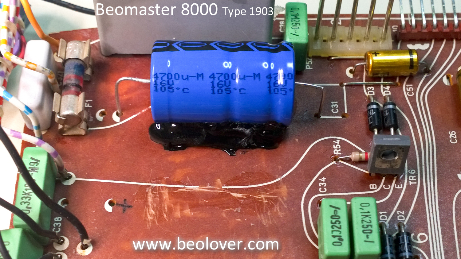
On the three, large axial capacitors I scraped off the old mounting glue to prepare for the new capacitors.

For this type of application a hot glue gun works great as the glue works fast and can always be removed in the future if necessary.
The metal shield box for the Beomaster remote control receiver is not too bad to remove but does require de-soldering four mounting tabs. Here is the box removed and the power supply board recapped.

The shield box is soldered back in place, the board connector solder joints are reflowed and this board is done.


Thanks for sharing this amazing posting
ReplyDeleteMy Beomaster 8000 is the first edition. On the left part of the PCB I can see that traces on the copper were manually removed. On the top side it has the same components. But your revision has them all nicely done with accompanying silkscreen. Mine is just a jumble of patched resistors, capacitors, transistors and two coils. That is a change that must have arisen very, very late in the process after they had mass produced the PCB's already. If I didn't know any better i'd think that someone had been mucking around, the quality is that bad.
DeleteThe failure on my Beomaster is in the middle of the PCB. Where the two large resistors and four transistors are squared. I can see from your board that it has also blackened. There is a lot of heat stress in this area and the transistors as well as the copper traces are prone to failure over time. On mine two transistors had completely cracked and the traces were broken off completely. I would suggest rebuilding this section and isolating the heat stress. It is a shitty design, a ticking time bomb.
ReplyDeleteI'm sorry, 6 transistors not 4.
Delete