
The original mica insulators and thermal paste work very well. However, due to the removal and reinstallation of these assemblies being so messy I have been switching to sil-pad thermal insulators. They are very easy to use and do not require the messy thermal paste...which seems to get on everything.
Here are the two boards with the components removed from the left channel board. While the components are removed I clean off the old dust that has accumulated over the years.

Here are the recapped boards.

The original trimmer resistors for (no-load) idle current and DC offset are replaced with multi-turn, sealed trimmer resistors.
For this application I have started to use sil-pad sheets instead of precut pads for the transistors. The sheets can be cut to cover a larger area which is what I like to do on these heatsinks because the mounting of the transistors can result in the shifting of components.


Installation of the transistors on the heatsinks is done by starting at the bottom and working to the top. The metal spring clips that hold the transistors in place have to slide over the top side of the transistor. The transistors shift a lot during this process and the spring clips are a little tricky to get into place. You can imagine the mess to clean up when thermal paste is used.

Here are the completed boards.

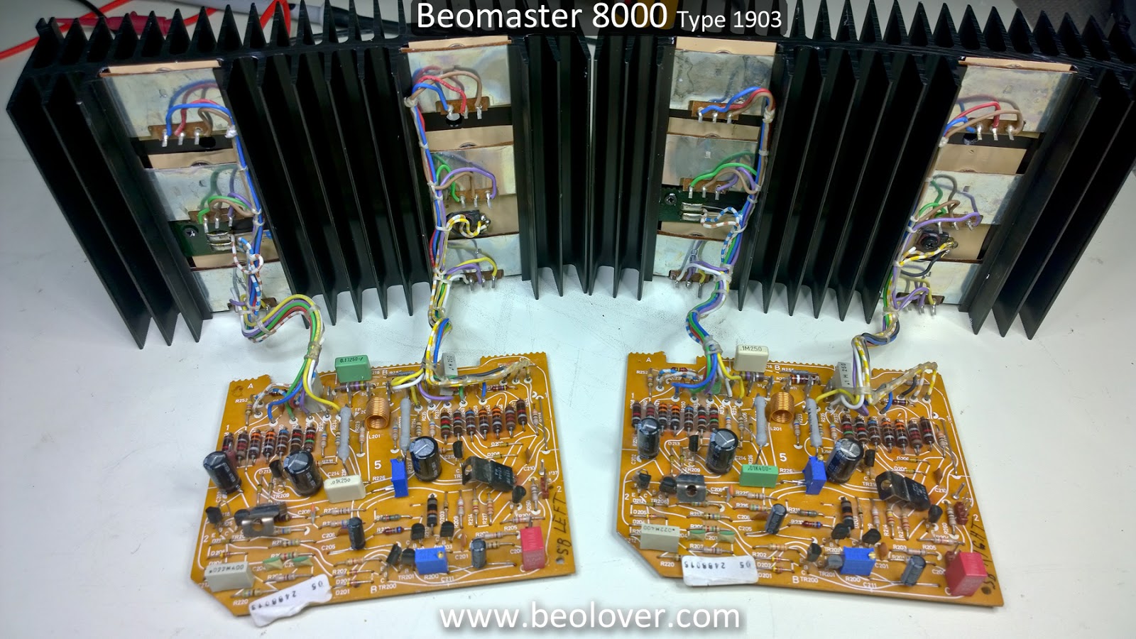
The next step is to perform the initial no-load, idle current adjustment on these two boards. These output amplifier boards can be powered and adjusted outside the Beomaster if you have the proper bench power supplies.
No comments:
Post a Comment
Comments and suggestions are welcome!