Featured Post

Beolover SyncDrive: DC Platter Motor Replacement for Beogram 4002 and 4004 (Type 551x and 552x)

Late Beogram 4002 and the 4004 (Types 551x and 552x), which have DC platter motors instead of the earlier synchronous AC motors usually suff...

Showing posts with label power supply board. Show all posts

Wednesday, September 12, 2018

Canada Beomaster 8000: Restoring the power supply board

The Rust-Oleum flat black paint has been applied on the left side of the cabinet as the final treatment to eliminate the rust areas I found.


While the paint is drying I performed the restoration on the Beomaster power supply board.


While I am working on this board I will change out the thermal protection on the ±15V and +5V regulators.

There is a 22uF, 25V capacitor under the metal cover for the remote control receiver circuit.


The large axial reservoir capacitors for ±15V and +5V have some rubbery glue that helps secure them in place.  I removed that glue and cleaned the board with alcohol.


...and here is the recap work and the remounted voltage regulators. I use black hot glue to secure the three large, axial reservoir capacitors. I will leave the metal cover off the remote control receiver until I can test that is works okay.


Monday, March 26, 2018

Beomaster 8000: Power Supply PCB Recap

The rust I found in the previous post focused my attention to that as the first order of business. 


Besides the +5 V, ±15V power transformer there were some rust spots on the bottom plate of the Beomaster cabinet.


I used a rust neutralizer on the bad areas of the transformer first. After that dried I used flat black rust preventative paint. Here is the cleaned up cabinet compartment where the +5V, ±15V transformer and power supply board go.


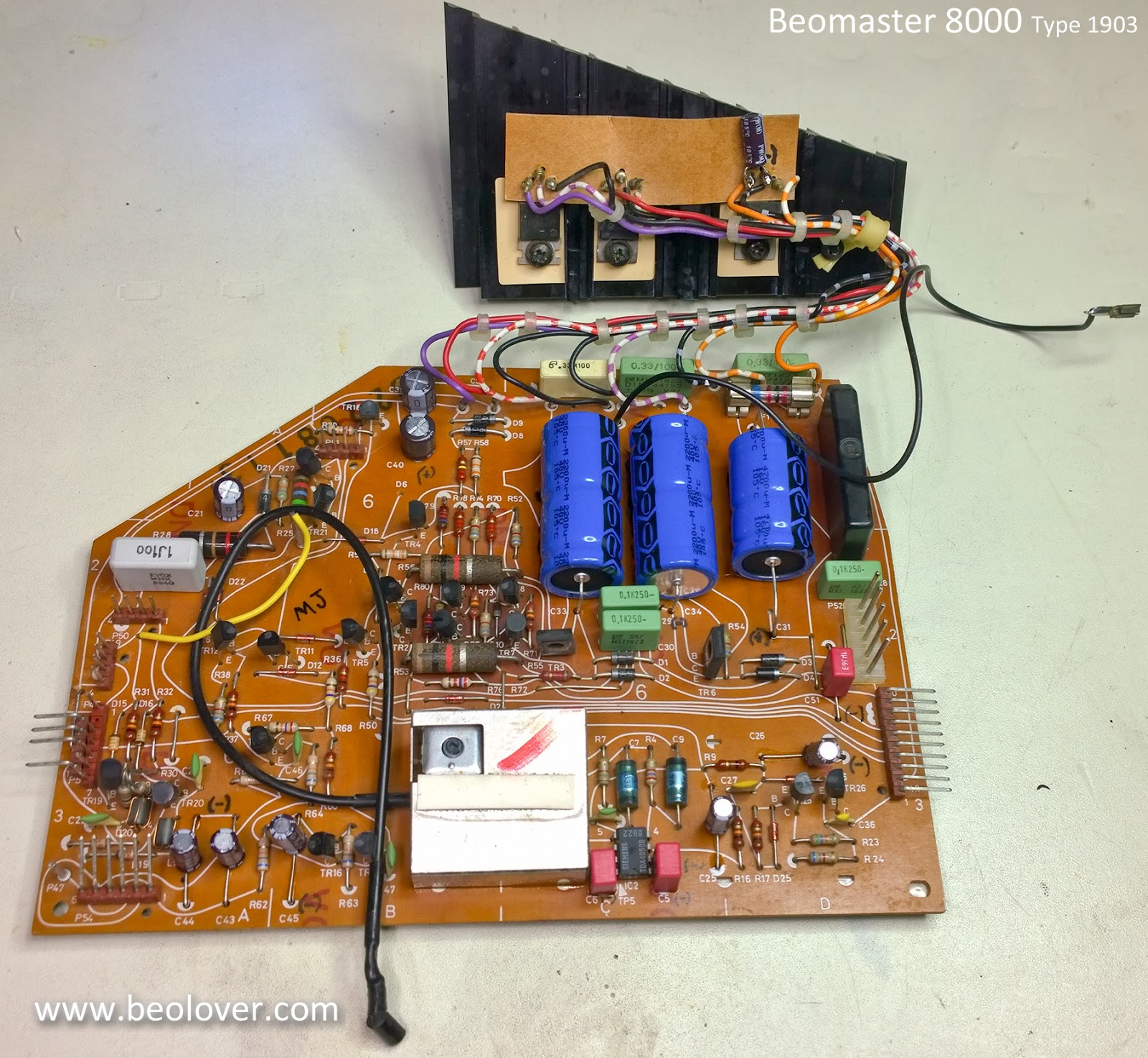
On the power supply board recap I cleaned dust and debris from the board and replaced the electrolytic and tantalum capacitors. This power supply board must have been worked on in the past. A few of the capacitors do not look like original capacitors what would have come from the Bang & Olufsen factory.  The large +5V, ±15V reservoir capacitors are not fixed to the board with double-sided tape like most of these boards.


I always like to measure the capacitors I remove just to see what condition they are in. Most of the capacitors are within tolerance but there are always quite a few that are borderline to way out of tolerance. 

Here is a good example of failed capacitors from the power supply board. One of the 10uF, 63V electrolytic capacitors measures 39uF now! A little off I would say ;-).


Failing the opposite direction this 22uF capacitor is only 11uF now.


The ESR values are also quite high on those two capacitors.
On capacitors that are still in tolerance we always change those to new capacitors as well. They have lived longer than expected but time is not on their side. With the Beomaster opened up it is best to replace them now and be assured they won't fail for another forty (or more) years.

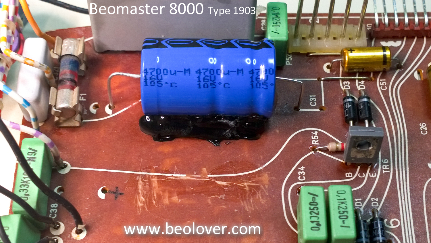
When replacing the +5V, ±15V reservoir capacitors I run a bead of hot glue along the bottom to secure the capacitors to the PCB so that won't move. The hot glue dries right away and can easily be removed if necessary.


Here is the power supply board with all of the capacitors replaced and new thermal insulators on the +5V, ±15V regulators. The metal shield around the remote control circuit is kind of a pain to remove and reinstall but that housed the failed 22uF capacitor so it is a necessary step.


With the cabinet and transformer cleaned up the parts are reinstalled.


It's starting to look like new again.


Wednesday, January 17, 2018

Beomaster 8000: Power Supply Board Recapping

The Beomaster 8000 Power Supply board restoration consists of changing out several electrolytic capacitors along with a couple of tantalum capacitors with new 105°C capacitors. As I normally do I use WIMA MKS capacitors where the capacitor value is less than 10uF.

Here is the before picture of the power supply board.


The capacitor replacement is pretty straight forward with the exception of one capacitor located inside the metal shield box on the board and the three large, axial capacitors (2200uF and 4700uF) that require some glue to secure.

There is also a separate heat sink assembly for three voltage regulators. I started with that assembly and replaced the lone 10uF capacitor. While I did that I decided to clean off the old thermal grease and change out the thermal insulators.


On the three, large axial capacitors I scraped off the old mounting glue to prepare for the new capacitors.


For this type of application a hot glue gun works great as the glue works fast and can always be removed in the future if necessary.


The metal shield box for the Beomaster remote control receiver is not too bad to remove but does require de-soldering four mounting tabs. Here is the box removed and the power supply board recapped.


The shield box is soldered back in place, the board connector solder joints are reflowed and this board is done.


Monday, January 15, 2018

Beomaster 8000: Removing the Output Amplifier Boards and Power Supply for Recapping

It has been quite a bit colder in the workshop the last week. Another cold front is arriving tonight but work must continue on the Beomaster 8000. I had to plug in an additional heater in the workshop to keep things toasty.

The next step in the restoration is to replace the electrolytic and tantalum capacitors on the two output amplifier boards and the power supply board. The reason I am doing those as a group is because of their physical location in the Beomaster.

The output amplifier board is identical for the left and right channels. The only difference is the color coding on the wires that connect to the speaker switches and the headphone jack.


I prefer to do the recap restoration work with the boards removed. In the case of these output amplifier boards they can also be tested outside the Beomaster by applying the necessary ±55V and +15V supply voltages.

Removal of the output amplifier boards requires removing the output transistors from the big heat sinks. It would have been nice if the output amplifier board had enough room to slide out the back of the cabinet without removing the heatsink mounted components. There are just too many wires in way.


It is worse on the left channel and the cabinet ledge for the lid damper (damper is removed in the photo) blocks any chance of the board sliding out.


So heat sink component removal it is.


The thermal paste for the transistors has usually started to dry out by now so I don't mind the exercise as it should ensure long term protection for the parts.


Here are the left and right output amplifier boards removed and ready for recapping.


This is also a good time to pull out the power supply board and its heat sink with the voltage regulators.


While these boards are out I will clean out any dust and debris from the cabinet where those components live. I like the feeling of knowing the Beomaster is clean like new again after the restoration.