It is a little difficult to capture (in a photo) what the rebuilt displays look like without the top lens cover on but the purpose of this test is to make sure all of the segments work. I usually run this burn-in test for twenty-four hours. That gives the new components a decent amount of time to fail if they are going to. I would hate to bundle everything up then have to disassemble the displays again.
To get to this point I removed the display modules from the Beomaster 8000 display board.
There are white and red tabs on the rear of the display board modules that hold the light guide and lens cover in place. Those tabs were originally part of the plastic sub-assemblies and melted down to secure the full display assembly. Since those cannot be removed and reused I have to just cut them off and use a different way to re-assemble the display modules after I rebuild them.
Here is the channel balance display board with the light guide and lens cover removed.
You can see these Bang & Olufsen display modules were very custom and the tiny, smd-like LED components cannot be replaced. We could locate the LEDs that have failed and just change those. However, that would result in a noticeable difference in the red illumination because the new smd LEDs are not exactly the same as the originals. They are very close but not the same. So it is best to change all of them. Another equally good reason to change all of the LEDs is because you can bet that if you only changed the failed LEDs the remaining good ones will likely fail as well. It's definitely better to get everything done while the Beomaster is open.
Here are some pictures from previous Beomaster 8000 display repairs that I use as a reference for this task.
This first picture shows the new smd LED component next to the original B&O LED.
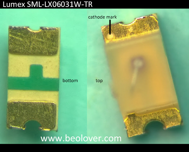
This picture shows identifier markings on the replacement smd LED component for reference.
The next step in the display rebuild after removing the light guide and lens cover is to cut out the original LED component.
I gathered a number of my Bang & Olufsen display modules that I have been wanting to rebuild and hope I can take the opportunity, while I am display repair mode, to get them done as well.
To prepare each display board for the new smd LED components I cut off the small solder pad that the original LED cathode rested on. That makes the gap between the anode and cathode pads better for the new components.
It is important to "tin" the solder pads before mounting the smd LED components. That will ensure a good, reliable connection.
Now for the actual mounting of the new smd LED components.
I have to say that this task is one of the most time consuming restoration tasks and requires a lot of patience to handle the smd LED devices while soldering them in place. The technique I use (and recommend) is to mount the smd LED components just on one lead. The reason is because the LED component must fit just right in the plastic light guide of the display module. There are always several LED components that I have to reposition slightly to correctly function inside the light guide. That also means the soldering process is to first position the smd LED with tweezers, solder one side to secure it, check the fit with the light guide, reposition if necessary and finally, solder in the other side. Quite labor intensive and hard on the eyes.
Here is a fit check of the smd LED in the light guide.
Once all of the new LED components have been fit checked I finish soldering the LEDs to the board.
Here is the completed FM tuner frequency display board.
On to the remaining three modules.
Another tip is to have a reference picture or (even better) a spare display board to use as a reference when mounting the new LED components. This task is very tedious so be disciplined to check the polarity carefully with each LED mounting. It is also another good reason to only solder one side initially.
Here is the completed LED replacement on the Beomaster 8000 selected source display board.
Note: The glare from my lighting off the no-clean flux residue makes a couple of the solder connects appear shorted.
The volume level display board is next.
Finally the channel balance display board. This board is the easiest to position the smd LED components on because it doesn't have pads where the LED mounts. However, the narrow trace makes soldering in the LED components a little tricky and this board is usually the one to have a connection problem.
Once the twenty-four hour burn-in test is complete I can reassemble the four display components and wrap up the display board. Then it will on to functional testing with this Beomaster.


No comments:
Post a Comment
Comments and suggestions are welcome!