Beolover provides professional maintenance and restoration services for vintage Bang&Olufsen stereos. We give one year warranty on parts and labor. All parts featured on the blog are available at our Store for DIY. Please, send an email for inquiries. Enjoy the blog!
As I mentioned, my Beogram 4004 was already restored and I use it regularly. The DC platter motor had been restored by Beolover back in 2021 and works great.
However, I love the idea of a self calibrating platter motor that is even more accurate and was ready to try it out in person.
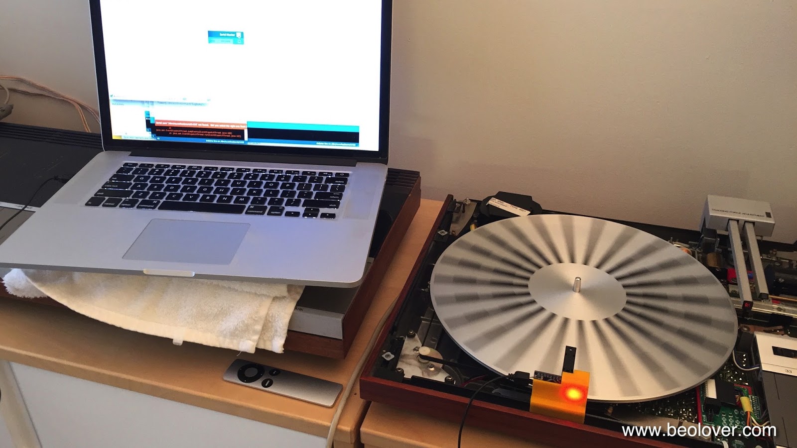
First, I remeasured the original DC platter motor using the Belovover RPM Tool v2. I wanted to have current values to compare the original platter motor with the SyncDrive.
This screenshot shows the measurements from the Beolover RPM Tool v2 being recorded on a PC.
I ran the measurements for twenty hours. Of course that is way longer than a platter motor would ever be run in normal use but it has been the length of time we usually collect RPM measurements on the Beolover Blog for comparison.
After saving off the measurement data for the original platter motor (at 33.33 RPM) I switched out the motor with the new Belover SyncDrive.
The changing of the motor is incredibly easy.
Here is the Beolover SyncDrive as received from Beolover.
Here is the connection point to the Beogram 4004 main board.
Here is the SyncDrive installed.
...and turned on by starting the platter turning and pressing one of the SyncDrive control buttons.
The SyncDrive came on showing me that my current settings have a 33.33 RPM value that is a little too fast. Not surprising since I hadn't run a calibration with the SyncDrive yet.
Here is the Beogram 4004 platter speed measurement with the SyncDrive installed and after it calibrated itself for 33.33 RPM.
How great is that? So easy.
My favorite features of the SyncDrive are its control buttons. I love being able to run automatic, self calibration for 33.33 and 45 RPM.
I also really like locking out the original Beogram control panel speed adjustment controls.
Now for the measurement comparison. Using the Beolover RPM Tool v2, I also measured the 33.33 RPM of the Beogram 4004 platter using SyncDrive. Again, I ran the measurement for twenty hours.
Looking at the measurement results you can see that both platter motors produce a consistent and controlled platter speed for twenty straight hours.
That is what I expected. After all, my original DC platter motor was restored by Beolover back in 2021 and should easily last another forty years.
However, you can also see how much tighter the RPM measurement is with the SyncDrive controlling the speed.
Also note that the mean for the original platter motor shows that it had drifted a bit slower than my original setting in 2021. It measured a mean value of 33.24 RPM. The 33 RPM trimmer on the Beogram 4004 main board could be used to readjust that along with a good measurement tool like the Beolover RPM Tool v2.
With the SyncDrive motor that type of readjustment is no longer necessary. You simply press the Auto Cal. button and two minutes later the platter speed is calibrated and locked in.
With either a Beolover restored DC platter motor or a Beolover SyncDrive, a Beogram 4002/4004 owner can get a beautifully functioning turntable. I just prefer (and appreciate) the technical achievement and performance of the SyncDrive.
Late Beogram 4002 and the 4004 (Types 551x and 552x), which have DC platter motors instead of the earlier synchronous AC motors usually suffer from dry motor bearings and/or bad spark snubbers. This often causes very noticeable RPM variations that ruin the listening experience. These motors can be restored by oil-infusing under vacuum, but even when restored, they do not measure up to the original AC platter motors or the later linear drives in the Beogram 8000 and 8002. Often there is significant RPM drift due to temperature variations and other environmental influences, and the analog feedback-based RPM control circuit causes fairly strong wow and flutter compared to the AC-motor Types and the 8000 series.
Once I realized the relative inferiority of the DC drive a few years ago (and also being slightly annoyed by restoring one DC platter motor after another..;-), I started working on an adequate replacement for these motors. I desired an upgrade for DC Type Beograms that would make them as good as the other models. This took me on a long and pretty interesting journey exploring different motor types and control approaches.
I finally settled on a brushless three-phase motor. The motor in the final design is custom manufactured for best performance and it is synchronously driven. The control system is able to measure the actual RPM of the platter, which enabled an auto-calibration feature that allows precise RPM adjustment.
I made a (rather long...sorry!...;-) video that explains the in and outs of the SyncDrive, demonstrates installation, use and gives a discussion of its performance relative to the other Beograms of the day. Enjoy:
The SyncDrive is available via the Beolover Store. Send an email to beolover@gmail.com if you are interested/have questions.
If you rather read than watch: Here is a short summary of the most important aspects:
The SyncDrive is an easy plug-and-play installation without the need for soldering (see video below). This is how the SyncDrive looks installed in lieu of the original motor:
The board bolts directly to the mounting posts of the original DC motor, and the electrical connections are made by a single wire harness that connects to the main board:
This picture indicates the essential features of the SyncDrive:
The speed sensor measures the platter speed from below, using the platter ribs in the same way the BeoloverRPM device uses them from above.
The user interface is activated by pressing any of the four buttons while the platter rotates. Once pressed, the indicator LEDs come alive and the interface is ready to interact. The buttons allow automatic calibration of the RPM and manual adjustment (33 and 45 are independently adjusted/calibrated depending on the actually selected RPM of the Beogram). Furthermore, the influence of the RPM panel above the keypad can be deactivated if desired. This can be useful if there are issues with the potentiometers in this panel, or if accidental RPM change is to be prevented.
I characterized the performance of the SyncDrive using the BeoloverRPM device, which allows precise RPM measurements and log them over time.
This shows a direct wow and flutter comparison between a restored DC-motor and the SyncDrive:
The measurement covers about 60 turns of the platter. The 'noise' in these spectra is caused by small variations of the spacing between the platter ribs. Since the BeoloverRPM device measures the time between the passing of ribs under its sensor, slight variations of the spacing introduce a measurement artifact. The two shown measurements were performed in the same Beogram with the same platter, i.e. have the exact same platter pattern. This allows a direct comparison. The red curve was measured with the SyncDrive installed, while the blue curve was measured with a restored original DC motor. The 'beating' pattern of the blue curve is an indication of the analog control system acting to keep the RPM constant. In essence, the RPM of the original motor 'meanders' around the 33.33 set point in an attempt to stay close. All feedback based control systems operate that way: The actual RPM is compared with the setpoint, and when the RPM is too low, the motor speeds up until it is measured too high, then the process reverses. This causes a wavy trajectory of the actual RPM around the set RPM. The art of feedback systems is basically to keep such variations at a minimum. The analog control system of the 4002 does a pretty decent job, but it is no match for the precision of synchronous motors, which do not rely on feedback, but rather on a very stable oscillator that determines the RPM top-down, and the motor simply 'obeys'. Precise oscillations can be generated with high accuracy, which makes such motors superior as platter motors.
This can be clearly seen when comparing the performance of the earlier AC platter motors found in Beogram 4002 550x Types and the original 4000. This graph shows the above two curves in comparison with a curve measured on a restored Beogram 4000, as well as the later 8000 and 8002 types:
The pink curve was measured on the 4000. It is clear that the performance is much better than the DC motor, which is a direct result of the synchronous operation of the can stack AC motor of the 4000, which is driven by an analog Wien precision oscillator. The slight waviness of the curve is most likely the result of the elastic coupling between the motor pulley and the platter causing a weak 'jo-jo effect'.
It is interesting to compare the performance of the belt drives with the later linear motors of the Beogram 8000 and 8002. Sonavor kindly contributed the green curves when I sent him the redesigned BeoloverRPM for testing. The overall RPM stability seems very similar to the 4000 and the SyncDrive. This is interesting since the linear drive in the 800x is a feedback based system. Here we see that feedback does not need to be bad if it is well designed. The linear drive benefits from the absence of a belt, which takes the elastic coupling out of the equation. A digital control system coupled with high-resolution feedback from an ~80 slots tacho disk seems to be sufficient for a fairly precise control that is much better than what was achieved with the analog control of DC motors. It is interesting to compare the two green curves: The much smoother 'platter pattern' of the 8002 is a result of its different platter design: The earlier 8000 still used a 4002 style platter, and consequently its platter pattern is similar to the measurements on the 400x. The (likely) etched platter of the 8002 seems to have more smoothly varying spacings between the platter ribs. I do not know how they really made these platters, but the smooth variations suggest a projection aberration during pattern generation for the etching process.
It is satisfying to see that the SyncDrive is matching up fairly well with the early 4000 and the later 800x.
When it comes to long-term stability the SyncDrive is actually better than the early 4000:
While the 4000 has a much better wow and flutter than the DC motor 4002, it has similarly strong longterm RPM drift. This is not a surprise, since its Wien oscillator is analog, and therefore also more easily affected by temperature variations. The SyncDrive compares favorably with a much smaller drift, courtesy of its digital control system. Unfortunately, we were not able to perform such measurements on Beogram 8000 and 8002s (yet!...;-). They shut down after 30 min if they recognize that no record is being played. I suspect that their RPM stability is also pretty good due to their digital control system.
In summary, I think the SyncDrive turned out to be a nice upgrade for any DC-motor Beogram, bringing them to AC-motor Beogram level (and likely even 8000 and 8002 level in terms of RPM stability).
I recently decided to redesign my BeoloverRPM device, which I started developing in 2015 for the detection of intermittent RPM variations mainly of DC platter motors. I thought after ~8 years it could use a little update in terms of ergonomics and performance. The original device was based on an Atmega 328P processor (aka 'Arduino') and this limited the performance a bit. I recently got into using the much more advanced ESP32 platform. This enabled a few new tricks due to the much higher speed.
The new BeoloverRPM can be placed on the aluminum panels for a quick and convenient RPM check
but it can also be configured for frame mounting when working on a Beogram:
This was achieved by a design where the frame adapters can be removed from the main device:
The BeoloverRPM comes with two frame adapters that have different spacing between the 'legs' that straddle the enclosure wall. B&O used slightly different enclosure designs with varying wall thickness.
Another significant update is that the BeoloverRPM now has two data acquisition modes:
The modes can be selected via buttons on the device. The 'slow' mode performs similar to the previous designs. It shows the RPM and min/max values on the display, and sends a RPM snapshot to the serial port every 10s (faster if the RPM changes quickly).
The 'fast' mode is new: It graphs all datapoints as they come in whenever a rib passes under the sensor. The display shows a rolling snapshot of the last 64 datapoints. The data is also sent out via the serial port. Here is an example measured on a Beogram 4004:
The main graph shows the data output from about 60 platter rotations. The graph shows a repeating pattern modulated by a sinusoidal envelope. Closer inspection yielded that the pattern repeats every 24 points, i.e. everytime the platter makes a full turn (there are 24 ribs on the platter). This can be explained by minute changes of the rib spacing (it varies by about 0.1%).
The sinusoidal modulation is a result of the feedback based RPM control of the DC platter motors of the later Beogram 4002 and 4004. Feedback control always results in an oscillation of the actual value around the set point. And that is what we see here. The analog feedback mechanism used by the later Beograms is based on time constants defined by capacitors and resistors, and this results in sinusoidal RPM variations.
Fascinating stuff!...;-).
I made a short video about the new BeoloverRPM. Enjoy!
After replacing the RPM trimmers, the RPM relay and the light bulbs in the RPM trimmer panel with LEDs, it was finally time to restore the DC platter motor of this Beogram 4004 (5526). This sequence is important, since one can only test the RPM stability performance of the motor properly after the entire RPM control circuit has been rebuilt. This shows the extracted motor:
The motor needs to be completely disassembled to get to the dried out Oilite bearings:
The bearings are the two small donuts on the black pad. I infused them with motor oil under vacuum:
The raising bubbles indicate that air is drawn from the porous brass bearing material. This creates space for oil to enter the bearing. After about 12-24 hours the process usually stops, at which point the bearings are again full of oil.
This shows the bearings after the infusion process:
After reassembling the motor I put it back into the deck and adjusted the RPM with the BeoloverRPM device:
Then I used the device to measure a RPM stability curve over 18 hours:
This motor showed an exceptionally stable RPM performance and can be considered ready for duty.
No design is ever final! And so I completely revised the enclosure and the base-attachments for my BeoloverRPM device that allows the precise measurement of the RPM of a Beogram. A very useful tool for adjusting the RPM when servicing the deck, or for occasionally checking the RPM as the main belt ages etc...
I sold a number of them since I made the first design available in 2015, but it turned out that the 3D printing of the enclosure had some reproducibility issues due to my use of dovetails to match the different attachable bases with the main unit. Dovetails are difficult to print with 3D printers due to the need for exact tolerances, and today's consumer 3D printers are just not there yet.
So after I ran out of the BeoloverRPM units I manufactured with the original design, I decided to completely redesign the enclosure with the limitations of 3D printing in mind to fill a recent order. Here are a few impressions:
This is what is in the box:
On the right is the BeoloverRPM device with its sensor sticking out to the right. It has a small display that shows the RPM and min/max values as they establish over time. It can also send a stream of data to a computer via the USB port allowing the generation of a RPM vs. time curve. This is very valuable if there are intermittent RPM issues, that are often difficult to discern or reproduce when just listening to records.
The parts on the left are the three different bases, that can be attached to the main unit. They allow clamping to different Beogram chassises (they come in different metal frame strengths) when the deck is in service position, or putting it on top of the enclosure next to the platter. The unit is powered via a USB cable connected to a computer. This cable is also used to extract the data stream from the unit for RPM logging if so desired.
This shows the frame clamp in action:
and this shows it on top of the enclosure using the flat base attachment:
The functionality of the redesigned BeoloverRPM stayed the same, i.e. the demonstration in my video still applies. Check it out here.
After rebuilding the DC motor and the control system of the Beogram 4002 (5514) that I am restoring right now, it was time to do a RPM performance test. I set up my BeoloverRPM device that allows the long-term logging of the platter RPM, and then did a 24 hrs test:
After the data was logged on my computer, I graphed it relative to a measurement that I took when I initially received the unit for restoration. This shows the two curves in comparison:
The red curve shows the performance before the restoration. The typical telltale sudden negative RPM spikes are visible that indicate failing brass sleeve bearings in the DC motor. This is very common for DC motor Beograms. In this case the spikes are still fairly moderate, but would have been audible since they are in the 1% range. The black curve shows the performance after rebuilding the motor and the installation of new RPM trimmers and RPM relay. The large spikes are gone and the variations are much smaller. There are still some variations, which are related to the intrinsically slightly erratic performance of the analog motor control system, which is affected by temperature changes and probably the moon phase (that was a joke...;-). Some Beograms show them others do not. At this point I do not have an answer why they sometimes occur. The good news is that they are fairly slow over time and also small enough that one cannot hear them. The short term 'wow and flutter' RPM changes (the high frequency 'noise' on these curves) are within the spec given in the service manual (0.05%). So this Beogram is back in business.
This is a follow up on yesterday's post about this Beogram 4002 (5513). I did an overnight RPM performance measurement with my BeoloverRPM device. This is the curve that I measured:
This result is pretty much as good as it gets for the DC motor versions. Minimal <0.05% variations over time satisfying the specifications stated in the service manual. The initial slope during the first couple hours is usually observed in the 551x and 552x models. I currently think it is a result of D13 (the Zener diode that stabilizes the DC motor supply) and R12 with which it forms a pretty stiff (i.e. high current) voltage divider to set the base voltage of TR2 heating up. After a while the temperature stabilizes at a certain value in equilibrium with the environment. The band gap change in the semiconductor of the Zener changes its Zener voltage and with that the motor slowly gets a bit more power until a sable condition is achieved. This 'ancient' voltage regulator design is a bit of a drawback of the DC motor versions of the 4002. But one should not get to worked up about it since the change is pretty slow, and only represents a total ~0.3% change, hardly noticeable by most listeners. I am thinking this phenomenon could possibly be alleviated via the adaption of the circuit to use a modern voltage regulator.
This is a follow up to my initial post about this Beogram 4002 (5513). In the meantime I did a RPM performance evaluation of the unit using my recently developed BeoloverRPM device.
This measurement clearly demonstrated the suspected sudden speed variations. This graph shows the RPM vs. time over an approximate 24 hrs period:
The sudden negative spikes suggest that the DC motor control system and the motor itself needs an overhaul.
I spent some time learning to program the small display that I integrated into my BeoloverRPM device that is useful for precision RPM adjustment as well as long term RPM stability characterization. I added min and max values as well as the total measurement time. Here is an impression of the display:
Quite high res and a nice contrast! However, guys of my age at least will need reading glasses to appreciate the small font...;-). Is life ever perfect??.
Anyway, I applied this new BeoloverRPM version to the Beogram 4002 that I just got going again and I performed a 12 hour RPM measurement. Here is the resulting graph:
This is a pretty good result about matching the specified 0.05% fluctuation number of the service manual. There are four spikes that exceed this specification (they are about 0.15% deviations). I have now measured a few 4002s with DC motor, and they all seem to have these spikes once in a while if one waits long enough. I think we see here the shortcomings of purely analog feedback systems. While these spikes are clearly measurable, they will be hardly audible. Most people can only detect changes of about 0.3 to 0.7%. So this Beogram should be fine for enjoying music.
This is an update to my earlier post about my BeoloverRPM device. It allows the measurement of RPM performance of Beogram 400x models over time. It is also very useful for precise RPM calibration. I now tested the original version on a few Beograms and I felt a display would make it much more pleasant to use for simple RPM adjustments in addition to the RPM vs. time serial port printout. Tonight, I finally figured out how to program a small display that I integrated into a modified enclosure of the unit. Here is an impression of the current setup:
Right now it just shows the actual RPM...I will fancify this readout a bit more and then this should be ready for primetime.
This is a follow up to my initial post about my BeoloverRPM device that can be used to quantify RPM stability and fluctuations in Beogram 400x and 8000x models (essentially all models that have 24 radial rubber strips on the platter).
I realized that a main application of the BeoloverRPM device is precision adjustment of the RPM in the analog 400x models. With a currently estimated precision of better than 0.03% the Beolover RPM device substantially outperforms the standard calibration discs that use the grid frequency from a light bulb, and also the 'AC motor Beogram way' of adjusting the motor frequency with an oscilloscope. Both of these 'traditional' methods yield maybe a precision of 1%. Similar errors arise when using a test record and a 3.3kHz or 1kHz tone...oscilloscopes are just not that great when it comes to measuring frequency precisely. A better way is to use a spectrum analyzer with a test record, but even this is fraught with significant errors due to non-centered records and noise issues.
In difference to these analog methods the BeoloverRPM device precisely measures the time that it takes for the black ribs to pass by the optical sensor, and microcontrollers are very good at measuring time precisely due to their quartz oscillators and their ability to do things very quickly. In fact it mimics the way the 800x models measure the RPM for their feedback control mechanism. And they are very precise at keeping 33.33 RPM over a long period of time. The BeoloverRPM is based on processor interrupts generated by the optical sensor, which essentially means that the error of the measurement comes mainly from the optical performance of the sensor. This remaining error is dealt with by doing a statistical real-time analysis of the measured data. The generated standard deviation output allows monitoring the quality of the measurement and/or the performance of the motor.
Using the BeoloverRPM device for RPM adjustment requires that it can be securely mounted on a Beogram while it is in service position so one can access the base RPM trimmers for the base RPM adjustment. This meant I had to come up with a different design of the system. I realized that it is best to clamp it directly on the metal frame of the enclosure. This allows to be close to the platter while giving a high mechanical stability to ensure a stable sensor position relative to the platter (correct distance is very important for the accuracy of the sensor).
Here are a few impressions of the current state of affairs. This shows the system in action:
Doesn't the power LED look pretty as it shines through he orange plastic print??...;-) The device hooks up to a laptop via a standard mini-USB flex cable. It simply bangs its data through the serial port in ASCII, which allows to use any terminal software on the computer to do the readout. I use the Arduino IDE's serial monitor. The device is now based on an Arduino Nano board with a CH340 USB interface. This makes it necessary to install the appropriate USB driver for this chip. Other than that it is 'plug and play'. The main advantage of this re-design, however, is that there is no more cable between microcontroller and sensor. This makes it much more straight forward with regard to assembly and use stability.
Here are a few detail shots. This shows the final design in front of the preliminary design studies of the plastic cradle (it is notoriously difficult to make a 3D print of a small part to fit something else precisely, and usually only extensive trial and error results in a satisfying fit):
I designed a spring clamp at the bottom for sticking it on the Beogram frame since the 4000 has a thinner frame than the later 4002/4 models. That way the cradle fits on both types:
The small slot is for pushing out the circuit board in case one needs to extract it. It makes a pretty solid press-fit with the cradle. Here is a detail photo how it clamps onto the Beogram frame:
A very solid fit for a precision RPM measurement! I want my customers' vinyls to play at the correct pitch! I am thinking about a 'consumer version' based on my initial design, which could have a direct LCD (or even a 'B&O style red LED 7-segment 4 digit back to the 1984 future style'...;-) display readout, so one could do a RPM check once in a while (yes, there is indeed some drift over time and depending on temperature in these classic analog designs) and compensate with the user accessible RPM trimmers on the control panel for continued precision listening enjoyment. This is Beolove!
Sadly, the Beogram 4002 that I restored a little while ago did not pass muster. It had initially come to me with an indication of sudden and gradual RPM fluctuations and I thought I had fixed the issue by replacing the RPM relay and the trimmers as well as the DC motor, which showed a strange feedback signal whenever the fluctuations occurred. But not so. While the phenomena were somewhat alleviated, some spontaneous variation still occurs occasionally. Per my customers description it happens maybe once per LP, i.e. it needs to be treated as an intermittent issue. Which are notoriously difficult to fix.
I decided I needed to be able to measure and quantify the issue before I would be able to attempt another stab at fixing it. The Beolover never gives up, but this one is a tricky one. The last few days I worked on designing the "BeoloverRPM" device, which now allows me to quantify and monitor the RPM of a Beogram with fairly high precision (I think it maybe about 0.03%) over time. I also implemented an automatic fluctuation detection mechanism based on monitoring the standard deviation of the measurement.
I designed a sensor head, which uses the black ribs found in the Beogram 400x and 800x models to detect the RPM of the platter. Here are a few impressions. The front is curved to fit the platter circumference, and the reflective optosensor unit extends via a fork over the platter
I implanted two M8 bolts into the back of the unit to give it some more weight so it would sit securely next to the platter:
Here is is shown in action measuring the platter of the Beogram 4000 that I just finished up:
It appears to be floating due to rubber feet inserted into the bottom of the body (I was inspired here by the Beogram 8000's rubber bumpers that dampen the impact of its hood when it closes)
The most crucial design parameter was the distance between sensor and measured features. Its optics are fixed, and I determined the best measurement resolution results at a distance of 9 mm. I printed several versions of the housing until I got that distance about right.
Once I had the sensor and verified that I could use it for RPM measurements I sat down and programmed an Atmega328p (aka Arduino) to measure the RPM and do some statistical evaluations. At this point the firmware is able to log the RPM and the standard deviation in timed intervals (10s in the example below). It also detects sudden deviations through monitoring the difference between the running mean of the standard deviation and the current standard deviation. This difference is quite sensitive and a proper threshold allows to hone in on a certain level of fluctuation.
Here is an impression of the printout that is generated:
The ***-marked % deviations were the result of slightly touching the platter with my finger a couple of times. It is interesting to note that the RPM shows as ~33.71 even though I calibrated the RPM of the Beogram 4000 using the AC motor frequency as specified in the Service Manual. It is obvious that this calibration is about 1% off. Naturally I wondered if a measurement error would be responsible for the discrepancy, but a test of the BeoloverRPM device on my Beogram 8000 revealed a proper measurement of 33.32 RPM, which is very close and possibly even at least partly a result of the Beogram 8000 being slightly off (the Service Manual specifies a 0.02% RPM accuracy).
As a next step I will implement an external trigger function for my oscilloscope that I can measure the vitals of a turntable at the moment a fluctuation occurs. Hopefully, this will allow me to figure out what the issue is with the fluctuating 4002! This is Beolove!