Featured Post

Beolover SyncDrive: DC Platter Motor Replacement for Beogram 4002 and 4004 (Type 551x and 552x)

Late Beogram 4002 and the 4004 (Types 551x and 552x), which have DC platter motors instead of the earlier synchronous AC motors usually suff...

Showing posts with label flutter. Show all posts

Wednesday, January 20, 2016

Beogram 4002 (5513): RPM Stability Test and an Updated Display on the BeoloverRPM Device

I spent some time learning to program the small display that I integrated into my BeoloverRPM device that is useful for precision RPM adjustment as well as long term RPM stability characterization. I added min and max values as well as the total measurement time. Here is an impression of the display:


Quite high res and a nice contrast! However, guys of my age at least will need reading glasses to appreciate the small font...;-). Is life ever perfect??. 
Anyway, I applied this new BeoloverRPM version to the Beogram 4002 that I just got going again and I performed a 12 hour RPM measurement. Here is the resulting graph:

This is a pretty good result about matching the specified 0.05% fluctuation number of the service manual. There are four spikes that exceed this specification (they are about 0.15% deviations). I have now measured a few 4002s with DC motor, and they all seem to have these spikes once in a while if one waits long enough. I think we see here the shortcomings of purely analog feedback systems. While these spikes are clearly measurable, they will be hardly audible. Most people can only detect changes of about 0.3 to 0.7%. So this Beogram should be fine for enjoying music.

Saturday, January 16, 2016

BeoloverRPM: Now with Display!

This is an update to my earlier post about my BeoloverRPM device. It allows the measurement of RPM performance of Beogram 400x models over time. It is also very useful for precise RPM calibration. I now tested the original version on a few Beograms and I felt a display would make it much more pleasant to use for simple RPM adjustments in addition to the RPM vs. time serial port printout. Tonight, I finally figured out how to program a small display that I integrated into a modified enclosure of the unit. Here is an impression of the current setup:


Right now it just shows the actual RPM...I will fancify this readout a bit more and then this should be ready for primetime.

Wednesday, December 23, 2015

BeoloverRPM: The Shop Version

This is a follow up to my initial post about my BeoloverRPM device that can be used to quantify RPM stability and fluctuations in Beogram 400x and 8000x models (essentially all models that have 24 radial rubber strips on the platter).

I realized that a main application of the BeoloverRPM device is precision adjustment of the RPM in the analog 400x models. With a currently estimated precision of better than 0.03% the Beolover RPM device substantially outperforms the standard calibration discs that use the grid frequency from a light bulb, and also the 'AC motor Beogram way' of adjusting the motor frequency with an oscilloscope. Both of these 'traditional' methods yield maybe a precision of 1%. Similar errors arise when using a test record and a 3.3kHz or 1kHz tone...oscilloscopes are just not that great when it comes to measuring frequency precisely. A better way is to use a spectrum analyzer with a test record, but even this is fraught with significant errors due to non-centered records and noise issues. 

In difference to these analog methods the BeoloverRPM device precisely measures the time that it takes for the black ribs to pass by the optical sensor, and microcontrollers are very good at measuring time precisely due to their quartz oscillators and their ability to do things very quickly. In fact it mimics the way the 800x models measure the RPM for their feedback control mechanism. And they are very precise at keeping 33.33 RPM over a long period of time. The BeoloverRPM is based on processor interrupts generated by the optical sensor, which essentially means that the error of the measurement comes mainly from the optical performance of the sensor. This remaining error is dealt with by doing a statistical real-time analysis of the measured data. The generated standard deviation output allows monitoring the quality of the measurement and/or the performance of the motor.

Using the BeoloverRPM device for RPM adjustment requires that it can be securely mounted on a Beogram while it is in service position so one can access the base RPM trimmers for the base RPM adjustment. This meant I had to come up with a different design of the system. I realized that it is best to clamp it directly on the metal frame of the enclosure. This allows to be close to the platter while giving a high mechanical stability to ensure a stable sensor position relative to the platter (correct distance is very important for the accuracy of the sensor).

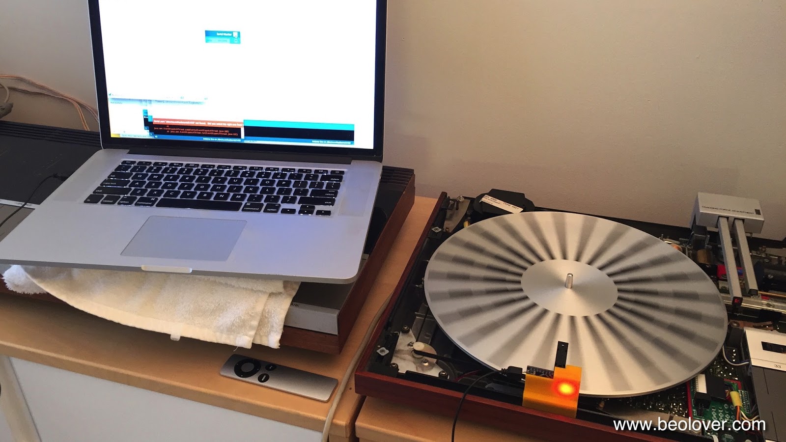
Here are a few impressions of the current state of affairs. This shows the system in action:

Doesn't the power LED look pretty as it shines through he orange plastic print??...;-) The device hooks up to a laptop via a standard mini-USB flex cable. It simply bangs its data through the serial port in ASCII, which allows to use any terminal software on the computer to do the readout. I use the Arduino IDE's serial monitor. The device is now based on an Arduino Nano board with a CH340 USB interface. This makes it necessary to install the appropriate USB driver for this chip. Other than that it is 'plug and play'. The main advantage of this re-design, however, is that there is no more cable between microcontroller and sensor. This makes it much more straight forward with regard to assembly and use stability.

Here are a few detail shots. This shows the final design in front of the preliminary design studies of the plastic cradle (it is notoriously difficult to make a 3D print of a small part to fit something else precisely, and usually only extensive trial and error results in a satisfying fit):

I designed a spring clamp at the bottom for sticking it on the Beogram frame since the 4000 has a thinner frame than the later 4002/4 models. That way the cradle fits on both types:

The small slot is for pushing out the circuit board in case one needs to extract it. It makes a pretty solid press-fit with the cradle. Here is a detail photo how it clamps onto the Beogram frame:

A very solid fit for a precision RPM measurement! I want my customers' vinyls to play at the correct pitch! I am thinking about a 'consumer version' based on my initial design, which could have a direct LCD (or even a 'B&O style red LED 7-segment 4 digit back to the 1984 future style'...;-) display readout, so one could do a RPM check once in a while (yes, there is indeed some drift over time and depending on temperature in these classic analog designs) and compensate with the user accessible RPM trimmers on the control panel for continued precision listening enjoyment. This is Beolove!


Thursday, December 17, 2015

BeoloverRPM: Beogram RPM Calibration Device

Sadly, the Beogram 4002 that I restored a little while ago did not pass muster. It had initially come  to me with an indication of sudden and gradual RPM fluctuations and I thought I had fixed the issue by replacing the RPM relay and the trimmers as well as the DC motor, which showed a strange feedback signal whenever the fluctuations occurred. But not so. While the phenomena were somewhat alleviated, some spontaneous variation still occurs occasionally. Per my customers description it happens maybe once per LP, i.e. it needs to be treated as an intermittent issue. Which are notoriously difficult to fix. 
I decided I needed to be able to measure and quantify the issue before I would be able to attempt another stab at fixing it. The Beolover never gives up, but this one is a tricky one. The last few days I worked on designing the "BeoloverRPM" device, which now allows me to quantify and monitor the RPM of a Beogram with fairly high precision (I think it maybe about 0.03%) over time. I also implemented an automatic fluctuation detection mechanism based on monitoring the standard deviation of the measurement. 

I designed a sensor head, which uses the black ribs found in the Beogram 400x and 800x models to detect the RPM of the platter. Here are a few impressions. The front is curved to fit the platter circumference, and the reflective optosensor unit extends via a fork over the platter

I implanted two M8 bolts into the back of the unit to give it some more weight so it would sit securely next to the platter:

Here is is shown in action measuring the platter of the Beogram 4000 that I just finished up:

It appears to be floating due to rubber feet inserted into the bottom of the body (I was inspired here by the Beogram 8000's rubber bumpers that dampen the impact of its hood when it closes)
The most crucial design parameter was the distance between sensor and measured features. Its optics are fixed, and I determined the best measurement resolution results at a distance of 9 mm. I printed several versions of the housing until I got that distance about right.

Once I had the sensor and verified that I could use it for RPM measurements I sat down and programmed an Atmega328p (aka Arduino) to measure the RPM and do some statistical evaluations. At this point the firmware is able to log the RPM and the standard deviation in timed intervals (10s in the example below). It also detects sudden deviations through monitoring the difference between the running mean of the standard deviation and the current standard deviation. This difference is quite sensitive and a proper threshold allows to hone in on a certain level of fluctuation.

Here is an impression of the printout that is generated:

The ***-marked % deviations were the result of slightly touching the platter with my finger a couple of times. It is interesting to note that the RPM shows as ~33.71 even though I calibrated the RPM of the Beogram 4000 using the AC motor frequency as specified in the Service Manual. It is obvious that this calibration is about 1% off. Naturally I wondered if a measurement error would be responsible for the discrepancy, but a test of the BeoloverRPM device on my Beogram 8000 revealed a proper measurement of 33.32 RPM, which is very close and possibly even at least partly a result of the Beogram 8000 being slightly off (the Service Manual specifies a 0.02% RPM accuracy).
As a next step I will implement an external trigger function for my oscilloscope that I can measure the vitals of a turntable at the moment a fluctuation occurs. Hopefully, this will allow me to figure out what the issue is with the fluctuating 4002! This is Beolove!