I was recently offered a nice looking Beogram 8002 from a gentleman in Oregon. After I received the unit I decided to restore it and while I had it opened up on the bench, I thought it would be a good moment for adapting the Beolover RIAA pre-amplifier design for this type Beogram. The 8000 series is popular among B&O collectors due to its unique linear induction platter motor, which drives the platter directly without any mechanical contact.
This shows the new Beolover RIAA pre-amplifier design:

I had to dramatically reduce the circuit dimensions due to the much less open interior space of the Beogram 8000 series. The design uses the exact same amplifier circuit I designed for my initial 400x pre-amplifiers, but the power supply is adapted to work with the 15V system of the Beogram 8000 series.
Implementation of this board requires opening up the Beogram. It is best to put it into 'service position', i.e. remove all significant components from the enclosure and set everything up on the bench:

This enables easy access to the ribbon cable that connects the output wiring to carriage and tonearm. This shows the end of the ribbon cable in its original state. The two left and right output cables are soldered to terminals on the ribbon end:

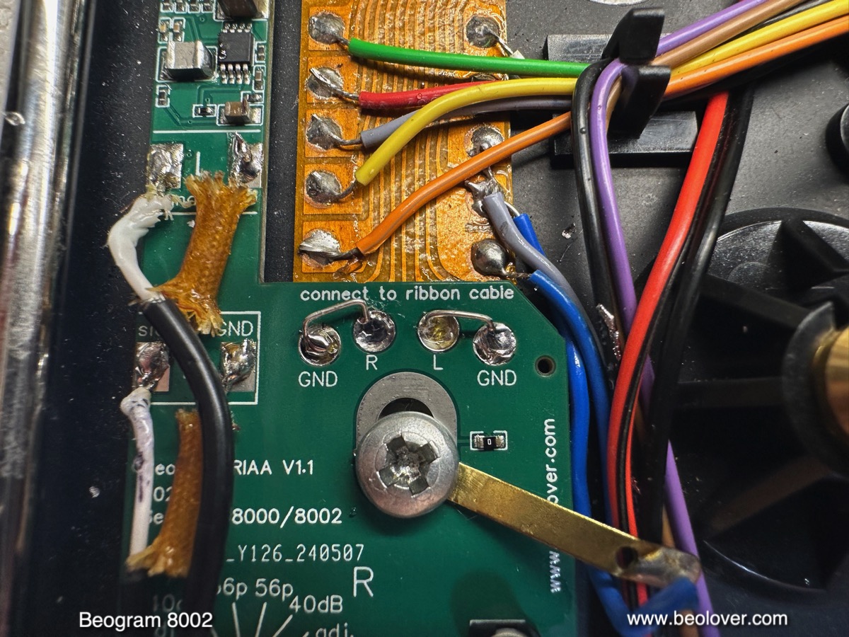
After removal of the wiring, a pattern of 4 circular solder pads is revealed:

The Beolover 800x RIAA pre-amplifier is soldered directly to these pads. It also bolts in mechanically using the bolt that connects the Beogram wiring to chassis:

The power connection to the board unfortunately requires routing a wire from 0TR1 that makes the stabilized +15V supply. This shows 0TR1 next to one of the carriage rods

The orange wire that connects to the emitter of this pnp TIP32 transistor carries about 21.3V from the rectifier. This voltage is used to power the RIAA board. The thicker red wire that is soldered to the solder terminal of the orange wire in the picture above is routed to the RIAA board and soldered to its 15V (min) terminal (see picture above).
After this fairly straight-forward installation, I characterized the circuit. Since the amplifier section of the board is identical to the version for the Beogram 4002 and 4004 series, I will only discuss the noise characterization here, which is specific to the Beogram 8000 series. The amplification and RIAA de-emphasis data is identical to what I discussed earlier in the post about the original 400x design.
When considering internal RIAA pre-amplifier designs the amount of electromagnetic interference (EMI) and back EMF from the platter motor leaking into the amplified signal is the most important quality factor after the performance of the pre-amplifier itself.
Since motors are notorious for feeding back voltage ripple into the power rails of their supply, it is necessary to take special precautions when designing an internal pre-amplifier that shares its power supply with a motor. RIAA preamps have their maximum gain of around 60dB in the lower frequency range due to the fact that lower frequencies are encoded at smaller amplitudes in the record grooves.
60dB corresponds to a 1000x voltage amplification. Unfortunately, platter motors usually generate voltage variations in exactly this low frequency range, i.e. even the smallest motor related voltage ripple can become very audible in the audio output signal if the amplifier supply is not carefully separated from the main supply of the turntable. As an example, a small 1mV motor ripple in the amplifier supply voltage could result in a 1V output ripple at 60dB amplification! This would be about the same volume level like that produced by a loud section on a vinyl record.
Characterization of the noise performance of the Beolover internal RIAA pre-amplifier for Beogram 8000 and 8002:
I used a QuantAsylum QA400 audio analyzer for these measurements. The QA400 is a predecessor of the currently sold QA403. The QA400 is essentially a very sensitive analog to digital converter (ADC) that is matched with software that can show a Fast Fourier Transform (FFT) of the audio signal. The resulting 'FFT spectra' essentially show the amplitude of individual frequency components of an audio signal plotted on the frequency axis. A simple example would be the FFT of a perfect undistorted 1 kHz tone. The FFT spectrum of this signal would be a single peak at the 1kHz frequency.
When measuring noise spectra with such a device, one gets spectra that show all the different frequency components of the noise. Ideal 'white noise' would yield a spectrum that has the same amplitudes for all frequencies, i.e. one would get a horizontal line above the frequency axis.
Real life situations are usually more complex and this brings us to the graph below:

This graph contains FFT spectra measured at the output of the Beogram 8002 deck before and after installation of the RIAA pre-amp board.
All five spectra were measured with the arm down and the platter running. In other words in the situation one encounters when playing a record.
The green spectrum at the bottom was measured before installing the RIAA pre-amp, i.e. represents the situation found in an Beogram 8002 in its original factory condition. The signal from the cartridge goes directly into the DIN7 output plug without any electronic circuitry in-between. Therefore the noise seen in this spectrum is purely related to the Johnson noise coming from the cartridge coils and the wiring hooked up between the cartridge and the QA400 audio analyzer, plus any EMI from external sources. The peak at 60 Hz is related to the EMI coming from the power system around the house where I did these measurements. It is very difficult to get rid of this peak in practical terms since this type of EMI is omnipresent in the environment and so would require complete Faraday shielding of the measurement setup. Luckily in FFT spectra one can easily identify it and then ignore it as a measurement artifact.
It is more interesting to look at the other end of this spectrum, where we see a number of small peaks. These peaks seem unique to the Beogram 8000 series since I did not see them in the corresponding spectrum measured when I characterized the original Beogram 4002/4004 version of this amplifier design.
While it is difficult to determine the origin of this noise signal with 100% certainty, my hypothesis is that it is interference from the linear platter motor. This motor is much more exposed than the fully shielded DC platter motors of the earlier Beogram 400x series and so it seems likely that these peaks are caused by EMI from the drive system.
This EMI seems to couple into the output signal via the traces on the ribbon cable that connects the tonearm wiring to the terminals where the output wires are connected. This ribbon cable is a mechanically elegant solution enabling carriage motion while maintaining wire connections, but is not shielded at all. In comparison the preceding 400x series Beograms bring shielded wiring right up to the base of the tone arm before it becomes exposed. This may explain the more quiet spectrum I measured for the 400x.
This hypothesis is supported by the measurement results on the RIAA pre-amp shown above the green spectrum. The first spectrum I measured (brown) was measured with the RIAA board soldered in, but the inputs connected directly to GND with small wire bridges. This is shown here:
This measurement allowed characterizing the noise that is contributed by the amplifier itself, since the signal at the inputs is 0V (GND). This is a common approach for testing the noise background of amplifiers.
Let's have a look at the spectrum. It basically replicates the low frequency peaks already seen in the green spectrum, which are measurement artifacts, but it does not show any of the high-frequency peaks seen in the green spectrum. This means that these spectral components in the green spectrum really come from 'before' the RIAA amplifier, i.e. from the wiring between cartridge and amplifier input.
This is clearly supported by the next spectrum (red) that was measured after removing the GND jumpers. In this case the signal from the cartridge was directly fed into the amplifier, and the amplifier duly amplified the noise.
In fact, when connecting the Beogram output to my amplifier, I was able to hear a weak noise signal from the speakers when turning up the volume to maximum. Music at this level would certainly have alerted our neighbors...;-). I.e. for all practical purposes this is a very weak noise signal that needs a lot of amplification to be audible. But the FFT spectrum mercilessly shows it in a fairly dramatic way!
To further characterize the significance of this EMI noise I did two more measurements, this time using 'Ultimate Analogue Test LP' from Analogue Productions. This test LP allows doing FFT measurements under actual vinyl record playback conditions. The blue spectrum in the graph was measured while playing Track 6 on Side 2 of this record ("Silent groove for bearing rumble and table isolation"). This track is a simple smooth V-groove without any encoded audio signal, i.e. it mainly produces vinyl groove surface noise (and of course a few klicks and pops). This essentially gives us the noise floor of a well-manufactured record. We see here that the blue spectrum has a considerably higher noise level than the red spectrum. The EMI noise only very weakly peaks through in this spectrum, i.e. it basically blends into the vinyl surface noise. I was not able to discern it anymore from the vinyl noise when listening to the track via my amplifier, even at very high volumes.
The final (black) spectrum in the graph was measured on Track 1 on Side 1 of the record, the "1kHz reference tone", which basically simulates actual listening conditions. This spectrum is dominated by a singular peak at 1 kHz, accompanied by its harmonics towards higher frequencies. These harmonics are mainly caused by distortions in the cartridge, which are typically around 1% (the amplifier itself has only about 0.012% harmonic distortions).
More interesting for this discussion is that the surrounding noise spectrum is even higher than the pure vinyl surface noise and in this spectrum the EMI noise is completely drowned out by noise coming from the 1 kHz track.
After this analysis it was time to enjoy this restored Beogram 8002 and just listen to some nice music. I selected one of my favorite records, "House Boat" by Volker Kriegel, which he recorded for the MPS (Music Produziert im Schwarzwald) label in 1978 (MPS 15.535). In my opinion one for the best Kraut Jazz records of all times. Maybe one of the best jazz records overall (I know...beauty is in the eye of the beholder...;-).
Anyway, a perfect record for a Beogram that originated from the early 1980s! Of course this record was cleaned ultrasonically before play with a CleanerVinyl ProXL setup to bring out its full analog vintage glory!
Here is an impression of the setup!...I always like playing the 800x turntables in their service position. Almost looks like one of those Very Expensive Modern Designs!...;-)

This sounded all very well! A pretty happy result. This Beogram can now smoothly be integrated with more modern B&O systems that do not have a phono input anymore.
This Beogram will need to remain in service position a little longer. I am working on one more upgrade, which I am hoping to feature soon in another post.
.jpg)
.jpg)

.jpg)


