Featured Post

Beolover SyncDrive: DC Platter Motor Replacement for Beogram 4002 and 4004 (Type 551x and 552x)

Late Beogram 4002 and the 4004 (Types 551x and 552x), which have DC platter motors instead of the earlier synchronous AC motors usually suff...

Showing posts with label pre-amplifier. Show all posts

Friday, May 22, 2026

Beogram 8000 (5613): Installation of Redesigned Internal Beolover RIAA Pre-Amplifier

I recently redesigned my internal RIAA pre-amplifier for the Beogram 8000 and 8002 to feature a set of dip switches that allow choosing between amplified and non-amplified signal routing. That makes it possible to switch the pre-amp off if an equipped Beogram is moved from an amplifier without RIAA to an amplifier with a phono input. 

My previous design required removing the pre-amp board to accomplish this, and I thought this needed to change. All my other RIAA designs have this capability. The RIAA circuit is unchanged in this latest iteration, i.e. my previous in-situ measurements apply. Read here about my distortion and frequency response measurements on this design.

This shows the new board:

The main change from previous versions is the addition of a 6-position dip switch:

The above picture shows the switches set to 'RIAA'. Flipping all six returns the Beogram to its non-amplified configuration, and it could be plugged into any standard phono input.

In the following, I will discuss how to install the board. It connects directly to the solder points at the end of the ribbon cable that connects to the carriage. I usually mark the right channel with a black marker so I don't get confused when it is time to solder the wires to the RIAA board outputs:
For clarity, here is a snippet from the service manual showing the terminals of the ribbon cable:
The terminals at the bottom are the left and right outputs.
The first step was unsoldering the right and left output wiring and cleaning the solder pads with a desolder gun:
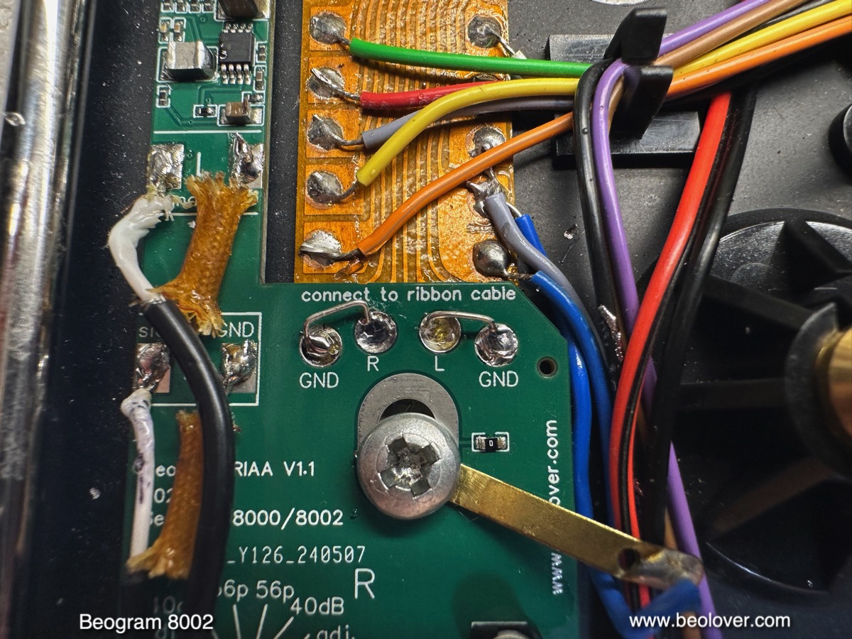
After removal of the mounting screw at the end of the ribbon cable assembly, I bolted the RIAA board in using the same screw and positioned it to overlap with the four solder pads of the output cables. Then I put a small amount of solder into each of the 'connection vias' of the board to make the connections between the RIAA inputs and the ribbon cable terminals:
The next step was to connect the L and R wires to the respective output terminals of the RIAA board:
I replaced the original woven insulation of the shield braids with modern shrink tubing (black) for a cleaner look.
The final part of the installation was connecting the RIAA board to its power supply.
Unfortunately, there is no power connected at the end of the ribbon cable, i.e. a separate wire needs to be installed to the 15V regulator. I connected a wire to the "15V" solder pad of the RIAA:
Note that the 15V label corresponds to the minimum voltage the RIAA needs for proper functioning. The maximum voltage allowed is 36V for this design. The next step is routing the wire to the voltage regulator PCB next to the front rod of the carriage. I recommend routing the wire along with the other wires beneath the subplatter. The critical routing points are labeled yellow in the photo below:

By feeding the wire under the plastic clips that hold the other wiring in place, it reliably avoids chafing with the sub platter. This shows the first of the clips (counted from the RIAA board):
And this the second when the wire emerges from underneath the subplatter:
This is how these two spots look with the subplatter installed:
The wire terminates at the input terminal of the TIP32 (0TR1) voltage regulator of the 15V rail. This terminal connects directly to the rectifier and main capacitor of the 15V rail and usually carries about 23V. I soldered the wire to the terminal, and this concluded the installation of the RIAA board!:
And then it was time to enjoy this redesigned RIAA pre-amp! I plugged the Beogram into the tape input of my amplifier and put on one of my favorite records, "Very Tall" by the Oscar Peterson Trio with Milt Jackson. This record was released in 1962 on Verve Records. I appear to have a re-issue from 1982 (UMV 2026).
Beolovely! This Beogram is now ready to be used with pretty much any modern amplifier or 'device' that still has a wired line-in!


Saturday, August 3, 2024

New Internal RIAA Pre-Amplifier for Beogram 8000/8002 - Installation and Characterization

I was recently offered a nice looking Beogram 8002 from a gentleman in Oregon. After I received the unit I decided to restore it and while I had it opened up on the bench, I thought it would be a good moment for adapting the Beolover RIAA pre-amplifier design for this type Beogram. The 8000 series is popular among B&O collectors due to its unique linear induction platter motor, which drives the platter directly without any mechanical contact.

This shows the new Beolover RIAA pre-amplifier design:

I had to dramatically reduce the circuit dimensions due to the much less open interior space of the Beogram 8000 series. The design uses the exact same amplifier circuit I designed for my initial 400x pre-amplifiers, but the power supply is adapted to work with the 15V system of the Beogram 8000 series.
Implementation of this board requires opening up the Beogram. It is best to put it into 'service position', i.e. remove all significant components from the enclosure and set everything up on the bench:
This enables easy access to the ribbon cable that connects the output wiring to carriage and tonearm. This shows the end of the ribbon cable in its original state. The two left and right output cables are soldered to terminals on the ribbon end:
After removal of the wiring, a pattern of 4 circular solder pads is revealed:
The Beolover 800x RIAA pre-amplifier is soldered directly to these pads. It also bolts in mechanically using the bolt that connects the Beogram wiring to chassis:
The power connection to the board unfortunately requires routing a wire from 0TR1 that makes the stabilized +15V supply. This shows 0TR1 next to one of the carriage rods
The orange wire that connects to the emitter of this pnp TIP32 transistor carries about 21.3V from the rectifier. This voltage is used to power the RIAA board. The thicker red wire that is soldered to the solder terminal of the orange wire in the picture above is routed to the RIAA board and soldered to its 15V (min) terminal (see picture above).

After this fairly straight-forward installation, I characterized the circuit. Since the amplifier section of the board is identical to the version for the Beogram 4002 and 4004 series, I will only discuss the noise characterization here, which is specific to the Beogram 8000 series. The amplification and RIAA de-emphasis data is identical to what I discussed earlier in the post about the original 400x design.

When considering internal RIAA pre-amplifier designs the amount of electromagnetic interference (EMI) and back EMF from the platter motor leaking into the amplified signal is the most important quality factor after the performance of the pre-amplifier itself.
Since motors are notorious for feeding back voltage ripple into the power rails of their supply, it is necessary to take special precautions when designing an internal pre-amplifier that shares its power supply with a motor. RIAA preamps have their maximum gain of around 60dB in the lower frequency range due to the fact that lower frequencies are encoded at smaller amplitudes in the record grooves.
60dB corresponds to a 1000x voltage amplification. Unfortunately, platter motors usually generate voltage variations in exactly this low frequency range, i.e. even the smallest motor related voltage ripple can become very audible in the audio output signal if the amplifier supply is not carefully separated from the main supply of the turntable. As an example, a small 1mV motor ripple in the amplifier supply voltage could result in a 1V output ripple at 60dB amplification! This would be about the same volume level like that produced by a loud section on a vinyl record.

Characterization of the noise performance of the Beolover internal RIAA pre-amplifier for Beogram 8000 and 8002:

I used a QuantAsylum QA400 audio analyzer for these measurements. The QA400 is a predecessor of the currently sold QA403. The QA400 is essentially a very sensitive analog to digital converter (ADC) that is matched with software that can show a Fast Fourier Transform (FFT) of the audio signal. The resulting 'FFT spectra' essentially show the amplitude of individual frequency components of an audio signal plotted on the frequency axis. A simple example would be the FFT of a perfect undistorted 1 kHz tone. The FFT spectrum of this signal would be a single peak at the 1kHz frequency.
When measuring noise spectra with such a device, one gets spectra that show all the different frequency components of the noise. Ideal 'white noise' would yield a spectrum that has the same amplitudes for all frequencies, i.e. one would get a horizontal line above the frequency axis.
Real life situations are usually more complex and this brings us to the graph below:

This graph contains FFT spectra measured at the output of the Beogram 8002 deck before and after installation of the RIAA pre-amp board.
All five spectra were measured with the arm down and the platter running. In other words in the situation one encounters when playing a record.

The green spectrum at the bottom was measured before installing the RIAA pre-amp, i.e. represents the situation found in an Beogram 8002 in its original factory condition. The signal from the cartridge goes directly into the DIN7 output plug without any electronic circuitry in-between. Therefore the noise seen in this spectrum is purely related to the Johnson noise coming from the cartridge coils and the wiring hooked up between the cartridge and the QA400 audio analyzer, plus any EMI from external sources. The peak at 60 Hz is related to the EMI coming from the power system around the house where I did these measurements. It is very difficult to get rid of this peak in practical terms since this type of EMI is omnipresent in the environment and so would require complete Faraday shielding of the measurement setup. Luckily in FFT spectra one can easily identify it and then ignore it as a measurement artifact.

It is more interesting to look at the other end of this spectrum, where we see a number of small peaks. These peaks seem unique to the Beogram 8000 series since I did not see them in the corresponding spectrum measured when I characterized the original Beogram 4002/4004 version of this amplifier design.
While it is difficult to determine the origin of this noise signal with 100% certainty, my hypothesis is that it is interference from the linear platter motor. This motor is much more exposed than the fully shielded DC platter motors of the earlier Beogram 400x series and so it seems likely that these peaks are caused by EMI from the drive system.
This EMI seems to couple into the output signal via the traces on the ribbon cable that connects the tonearm wiring to the terminals where the output wires are connected. This ribbon cable is a mechanically elegant solution enabling carriage motion while maintaining wire connections, but is not shielded at all. In comparison the preceding 400x series Beograms bring shielded wiring right up to the base of the tone arm before it becomes exposed. This may explain the more quiet spectrum I measured for the 400x.

This hypothesis is supported by the measurement results on the RIAA pre-amp shown above the green spectrum. The first spectrum I measured (brown) was measured with the RIAA board soldered in, but the inputs connected directly to GND with small wire bridges. This is shown here:

This measurement allowed characterizing the noise that is contributed by the amplifier itself, since the signal at the inputs is 0V (GND). This is a common approach for testing the noise background of amplifiers.
Let's have a look at the spectrum. It basically replicates the low frequency peaks already seen in the green spectrum, which are measurement artifacts, but it does not show any of the high-frequency peaks seen in the green spectrum. This means that these spectral components in the green spectrum really come from 'before' the RIAA amplifier, i.e. from the wiring between cartridge and amplifier input.
This is clearly supported by the next spectrum (red) that was measured after removing the GND jumpers. In this case the signal from the cartridge was directly fed into the amplifier, and the amplifier duly amplified the noise.
In fact, when connecting the Beogram output to my amplifier, I was able to hear a weak noise signal from the speakers when turning up the volume to maximum. Music at this level would certainly have alerted our neighbors...;-). I.e. for all practical purposes this is a very weak noise signal that needs a lot of amplification to be audible. But the FFT spectrum mercilessly shows it in a fairly dramatic way!

To further characterize the significance of this EMI noise I did two more measurements, this time using  'Ultimate Analogue Test LP' from Analogue Productions. This test LP allows doing FFT measurements under actual vinyl record playback conditions. The blue spectrum in the graph was measured while playing Track 6 on Side 2 of this record ("Silent groove for bearing rumble and table isolation"). This track is a simple smooth V-groove without any encoded audio signal, i.e. it mainly produces vinyl groove surface noise (and of course a few klicks and pops). This essentially gives us the noise floor of a well-manufactured record. We see here that the blue spectrum has a considerably higher noise level than the red spectrum. The EMI noise only very weakly peaks through in this spectrum, i.e. it basically blends into the vinyl surface noise. I was not able to discern it anymore from the vinyl noise when listening to the track via my amplifier, even at very high volumes.
The final (black) spectrum in the graph was measured on Track 1 on Side 1 of the record, the "1kHz reference tone", which basically simulates actual listening conditions. This spectrum is dominated by a singular peak at 1 kHz, accompanied by its harmonics towards higher frequencies. These harmonics are mainly caused by distortions in the cartridge, which are typically around 1% (the amplifier itself has only about 0.012% harmonic distortions).
More interesting for this discussion is that the surrounding noise spectrum is even higher than the pure vinyl surface noise and in this spectrum the EMI noise is completely drowned out by noise coming from the 1 kHz track.

After this analysis it was time to enjoy this restored Beogram 8002 and just listen to some nice music. I selected one of my favorite records, "House Boat" by Volker Kriegel, which he recorded for the MPS (Music Produziert im Schwarzwald) label in 1978 (MPS 15.535). In my opinion one for the best Kraut Jazz records of all times. Maybe one of the best jazz records overall (I know...beauty is in the eye of the beholder...;-).
Anyway, a perfect record for a Beogram that originated from the early 1980s! Of course this record was cleaned ultrasonically before play with a CleanerVinyl ProXL setup to bring out its full analog vintage glory!
Here is an impression of the setup!...I always like playing the 800x turntables in their service position. Almost looks like one of those Very Expensive Modern Designs!...;-)

This sounded all very well! A pretty happy result. This Beogram can now smoothly be integrated with more modern B&O systems that do not have a phono input anymore.
This Beogram will need to remain in service position a little longer. I am working on one more upgrade, which I am hoping to feature soon in another post.


Tuesday, April 11, 2023

Beogram 4002 (Type 5504): Installation of Newly Adapted Beolover RIAA Pre-Amp

After recently redesigning the Beolover internal RIAA pre-amplifier for DC-motor Beogram 4002/4 turntables, and adapting the circuit for the Beogram 4000, it was finally time for the next chapter in this design process: Adaptation of the circuit for the AC motor Beogram 4002.

The owner of the 4002 (5504) that I just restored asked me to install the RIAA and so his Beogram will be the first AC-motor 4002 featuring a Beolover RIAA!

This shows the new board:

The input jack of the board connects to a replicated Beogram style plug via a multi-lead wiring harness. The output jack on the right matches the plug that is on the output cable of this type Beogram.
Due to the large footprint of the output jack, I decided to give this design bypass switches instead of the two completely separate signal paths via separate input and output jacks that I chose for the DC motor board. The switches allow connecting the Beogram to a standard Phono input without re-installing the original output board.
A look at the backside of the board reveals a separate grounding wire that allows connecting the board ground to the chassis of the turntable. This has shown in my experiments to help if there are any 50Hz hum issues (but in some cases it also causes hum, so this is something to be tried out in your particular setup):
Here is a look at the board next to the original board that I restored when I finished this turntable:
For installation of the Beolover RIAA board, all that is required is unplugging the board

and replacing it with the Beolover RIAA board:

The only difference is that the ground wire needs to be bolted to the 'cable clamp' bolt:
This shows the board after bolting the keypad back in:
It is designed that the control features are accessible with the keypad cluster installed. This allows setting the gain and switch between RIAA and non-amplified operational modes.


Sunday, March 26, 2023

Beogram 4000: Installation of Newly Designed Beolover RIAA Pre-Amplifier Board

****Update: The Beolover Beogram 4000 internal RIAA pre-amp is now available at the Beolover Store*****

In the past I had a few inquiries for an internal RIAA pre-amplifier board for the Beogram 4000. So when the recent re-design of the Beolover RIAA pre-amplifier for DC motor Beogram 4002 and Beogram 4004 finally came together, I decided to adapt the circuit for the Beogram 4000. 

The owner of the Beogram 4000 that re-visited my bench last week for a little warranty issue decided to let me install the new board in his unit.

This post shows how I installed it. For measurement data, please, check out my post about the characterization of the 4002/4 version, which has the exact same circuit.

This show the board in its current form:

It is still a prototype board and has a couple features that will be removed for the final version. I was not sure how I would power the amplifier in the 4000 since it is set up differently compared to the later 4002/4. I ended up connecting to the 24V rail. The amplifier section of the board is not affected by this, and so this version is already suitable for regular use. 

The 4000 is still fully wired with directly soldered harnesses. This means the board needs to be soldered into place in the 4000. In the 4002/4 the board is simple plug and play due to their more modern design with wire-to-board connectors. Due to the 'permanent' soldered installation I gave this board two switches, with which one can route the output signal through the amplifier, or bypass it in case a traditional Phono amplifier input will be used.

Anyway, let's do the installation! Exciting!:

This shows the output terminal of the Beogram 4000 with the red switch that I installed last year to enable connecting signal and system grounds if there is a hum issue.

Here a detail-photo of the terminal:
The first step was to remove the output cable and the switch from the terminal:
Then I removed the screws that bolt the terminal to the enclosure bottom:
The Beolover RIAA board simply screws on top of the terminal 'bar'. The mounting holes are slots, i.e. the board can be pushed up to the wire terminals for directly soldering it to the contact pads on the board:
The next step is to solder the terminals to the matching board pads:
Then the output cable can be soldered to the output terminals of the RIAA board. They are spaced exactly like the terminal pads, i.e. the output wiring does not need to be modified, and it can directly be soldered in place:
The last step is to connect the red power wire to the 24 rail of the Beogram. A convenient spot is on the main board, where the 24V rail comes in on another red wire.

The strange 6-diode contraption in the back is the Beolover's approach to replacing the Wien oscillator light bulb with a diode based Automatic Gain Control for easy oscillator startup....but that is an entirely different story...;-)

The final step is to pull the output cable a bit further out of the enclosure in the back since the RIAA board pushes the wire terminals a few cm towards the back of the enclosure.

And that is it. This Beogram 4000 can now directly be connected to any modern receiver without Phono input.

Saturday, February 18, 2023

Completely Re-Designed RIAA Pre-Amplifier for Beogram 4002/4 (Types 551x and 552x)

As usual, it took a bit longer than planned. The Beolover is definitely used to the concept of 'delayed gratification'!...;-).

But here it is: The completely re-designed Beolover internal RIAA pre-amplifier for the DC-motor Beogram 4002 and 4004 (Types 551x and 552x). An AC version will be coming up soon based on the same design.

When it comes to RIAA preamplifiers the important benchmarks are:

  • How accurate is the RIAA de-emphasis? How closely tracks the pre-amp the standard RIAA curve?
  • What is the noise floor of the pre-amp?
  • How much distortion ("THD" - Total Harmonic Distortion) does the pre-amp inflict on the amplified signal?

The 'internal pre-amplifier' situation has an additional benchmark that is not shared with external or in-amplifier pre-amps:

  • Is there any interference from the platter motor? RIAA pre-amps have gains up to 60dBV, which corresponds to an amplification by a factor 1000. This means that even small ripple in the power supply will generate audible signals in the output. Electromagnetic loads like motors are notorious for introducing ripple and disturbance on the power rails due to their back-"electromotive force" (back-EMF) that is caused by the generation of a voltage as the motor spins. This voltage is polarized opposite the voltage that drives the motor. Additionally, brushed motors like the DC motor in the Beogram Types 551x and 552x tend to emit significant voltage spikes due to the instant reversal of the coil polarities, which is the reason that these motors have spark suppressors in the first place.
It turned out that especially the last point is not trivial. And this is the reason it took me a while to come up with a solution that is on par with quality commercially available external phono pre-amplifiers.

My new design is a 'plug and play' solution that simply replaces the entire original output PCB. This picture shows a rebuilt original board (right) and my new design (left) in direct comparison:
The new RIAA board has the same form-factor like the original PCB, i.e. can be installed by simply replacing the original board. The new design also has the appropriate connectors for installation in a Beogram 4004 that has an additional connector underneath the keypad. I also included a connector for direct connection to the Beolover Commander remote control module if it is to be used in a 4004 together with the RIAA pre-amplifier.

The BeoloverRIAA board can also be configured as a standard output board bypassing the RIAA amplification. For this reason I implemented a dual 2x9 input header and two output sockets:

The lower row is used for the RIAA signal path, whole the upper row serves as connector for the conventional non-RIAA path.

This shows the board installed in a 4002:
With the 'set' switches above the red standoff the gain can be selected and the B&O standard 56p input capacitance can be connected if desired. The gain can be switched between a pre-set 40dB mode, and an adjustable mode where the gain can be tuned from ~30-50dB. This can be helpful if one wants to use a vintage cartridge where one channel is a bit weaker, or to level the Beogram output with other input sources connected to the amplifier.

The filter sections of the RIAA amplifier section, shown here,

are built with quality 2% tolerance Panasonic Polyphenylene Sulfide (PPS) Film capacitors and 1% resistors. The use of PPS capacitors enables ultra-low distortion figures. PPS capacitors have an only very weakly voltage dependent capacitance, which keeps non-linearities to a minimum. The frequency response of each channel can be tuned with two trimmers, one for bass and the other for treble. This can be helpful if there is a deviation from the ideal RIAA behavior due to component tolerances or aging.

Since the Beogram only has a uni-polar power supply, the amplifier had to be built with a virtual ground to enable AC signal amplification. This posed a challenge due to the noise introduced on the power rail by the platter motor, as well as the tendency of virtual grounds to raise the noise floor of the amplifier. Only the use of a buffered precision virtual ground made it possible to achieve a noise floor that is similar to external RIAA amplifiers, and to completely eliminate motor interference.

Characterization of the BeoloverRIAA pre-amplifier:

In the following I will show some key measurement data that demonstrates the performance of this amplifier. 

Measurement Conditions:

I used a QuantAsylum QA400 audio analyzer for my measurements. The QA400 is a predecessor of the currently sold QA403 (if it is available at all). It essentially is a very low noise high resolution Analog-to-Digital converter (ADC) integrated with a quality waveform generator, which in turn is basically a Digital-to-Analog converter. This combination allows measuring the 'transfer function' of an audio device by sending a suitable input signal into the device and measuring what comes out at the other end. The beauty of it is that the QA400 can analyze the output signal via computer software that generates a Fast Fourier Transform (FFT) of the signal. This yields a spectrum that shows the output signal divided up into its individual frequency components. This goes back to the fact that any signal can be synthesized by a combination of (or 'integral' over) sine waves of appropriate frequency and amplitude. 

How were things hooked up? The input signals from the waveform generator were fed into the amplifier via BNC-to-minigrabber cables (which is the reason that there is a bit of 60Hz interference in these spectra). The output signal was fed back into the QA400 inputs by connecting the standard RCA output cable of the Beogram with RCA-to-BNC adapters to the inputs of the QA400. 
During all measurements the platter was turning and the arm was lowered next to the platter with a cartridge mounted. This was done to characterize the amplifier in-situ under realistic operational conditions.

Frequency Response Measurement - Does the Amplifier match the standard RIAA de-emphasis curve?

The frequency response of any RIAA pre-amplifier is key to a faithful reproduction of the sound stored on vinyl records. It is in my opinion the most important characteristic since it really is the only characteristic that affects the 'sound' of the pre-amp. From a scientific point of view any discussion of the 'sound of an amplifier' are in reality a discussion of the frequency response, and its deviation from the ideal behavior.

I measured the frequency response using the "FR" function of the QA400 audio analyzer. I used the 'white noise' stimulus, which basically sends pulses of white noise into the input of the amplifier and simultaneously measures the Fourier spectrum of the transmitted signal at the output. 
Since white noise is composed of all frequencies at the same amplitude, the output spectrum can directly be matched to a standard RIAA curve since it is a direct 'fingerprint' of the transfer function of the amplifier.
I obtained the standard RIAA curve in conveniently tabulated form from here and then loaded it into my data processing software. This shows the result of the measurement for both left(red) and right(blue) channels in comparison to the dotted standard RIAA curve:
Essentially both right and left curves are identical and they match the RIAA curve very well. There is a bit of a 60Hz noise due to the partially unshielded input connections. I do not know exactly what the 'wiggle' between 20 and 30Hz means, but I think it is a measurement artifact. 

Total Harmonic Distortion (THD) Measurements:

Total Harmonic Distortion (THD) of an amplifier represents the percentage of the output signal that is composed of harmonics of the input signal that were not present at the input. The origin of such distortions is usually the non-linearity of components in the amplifier circuit. Especially capacitors have non-linearities since their capacitance changes with the applied voltage. This distorts sine waves during the amplification and filtering process, and that means that the FFT of such a signal will show higher harmonics related to the input signal. In order to see and quantify this measurement, a pure single frequency is sent into the amplifier and then the output signal is evaluated for the presence of harmonics. An evaluation and summation of the individual intensities of the harmonics and subsequent comparison with the principal frequency yields the distortion as a percentage of the principal signal.

This graph shows the THD measurements I performed with the pre-amplifier:
a) Measurement of THD using the QA400 internal waveform generator (red spectrum):

This measurement basically corresponds to the above 'best case scenario', where a high quality almost ideal 1kHz signal is fed into the amplifier and the response is measured. Since the input signal is nearly perfect, all distortions that are measured can be assumed to have been introduced by the amplifier, and that makes it easy to calculate the THD as a percentage of the primary signal. 
The red spectrum was measured with the QA400 internal signal generator set to 1kHz. I adjusted the output volume of the generator to get an exact 0dBV (=1.0Vrms) output signal from the RIAA pre-amp. This seems to be the standard measurement condition employed by most amplifier manufacturers, although they are often quite circumspect with regard to how their measurements were done exactly.
It is obvious that there is only a very limited degree of higher harmonics present in the red spectrum. The THD evaluation function of the QA400 reported a THD value of only 0.012%. This is similar to the numbers stated for many commercially available external RIAA preamps.

b) Measurement of THD playing a 1kHz tone on a test record (blue spectra):

I wanted to understand what this THD result meant in practical terms, and so I wanted to see how the above best case scenario would compare with an actual 'record playing situation'. A while ago I had purchased a copy of the 'Ultimate Analogue Test LP'. It features a "1kHz reference tone 7cm/s lateral in phase (mono)" track on side one.
I think it is supposed to represent a reference signal representing the typical maximum signal level as encountered on many records. I played this track with two vintage B&O cartridges that I use for regular listening, and that in my opinion still sound pretty good.

1) MMC20CL cartridge:
The dark blue trace was measured with a MMC20CL. We see that there is a significant amount of harmonics in this spectrum. The QA400 THD evaluation yielded 0.95%, i.e. about 86 times more distortion than it determined for the red curve. 
2) MMC20EN cartridge:
The second measurement with a MMC20EN cartridge was even worse, coming in at 1.2% distortions.

If you wonder how the QA400 determines these percentages, this can be rationalized by looking at the ratio between 1kHz principal peak and the first harmonic at 2kHz. For the test record measurements a difference of about 40dBV is read from the graph. 40dBV corresponds to a 100x signal amplitude difference, which means that the 1st harmonic signal has about 1% Vrms amplitude compared to the 100% principal signal. 
Looking at the red curve, a difference of about 90dB is read off the graph, which corresponds to a factor 31622 between the signals. Expressed as a percentage it would mean 0.03%, which is pretty close to the 0.012% number the QA400 spat out. This may give an idea about the potential error bars on these measurements, since the 1st harmonic peak is pretty close to the noise level, i.e. there is probably some degree of uncertainty in these measurements, especially when the percentages get small.

Luckily, it does not really matter whether the amplifier distortion is 0.012 or 0.03% since the distortion introduced by the vinyl and the cartridge is about two magnitudes larger. The above measurements just mean that the amplifier is certainly good enough in the THD department for a faithful reproduction of vinyl records.

Determination of the 'noise floor'

On to the last set of measurements: The determination of the noise floor.

The graph below shows a series of measurements under different conditions that allow exploring what is going on:


Let's start with the green spectrum at the bottom. This spectrum shows the situation with the standard output board without RIAA amplifier. It basically represents the noise that generated by the cartridge and the wiring, which is thermal noise from electrons bouncing around in the cartridge coils and the connecting wires, which represents a small fluctuating voltage in the uV range.
This 'natural' noise floor is amplified in the RIAA pre-amp when the signal from the cartridge is routed though it. 

I also measured the noise that exclusively comes from the amplifier itself. This is usually done by connecting the input to GND. The resulting spectrum is the black one. We see a drop of ~40-45dBV between 20 and 20000Hz. This about corresponds to the RIAA gain drop between these corner frequencies, and means that the thermal white noise at the input of the amplifier is simply amplified by the frequency dependent gain of the amplifier.
 
The next measurement was the blue spectrum. It was measured after removing the GND connection and lowering the arm next to the platter with the platter running. This curve is similar to the black spectrum at lower frequencies, but up to 10dBV higher towards 20kHz. This is probably a result of the thermal noise from the cartridge coils being added to the signal.

A big question of any 'internal' pre-amp design is: Does the platter motor add unwanted noise into the output signal of the pre-amp? The good news is that my design approaches are able to completely quench any noise coming in from the Beogram power rails. The ripple rejection of my approach is very strong. Earlier versions of my design had sizable motor peaks in their noise spectra between 30 and 40Hz and between 100 and 120Hz. The motor noise was clearly audible at high volumes. Not so anymore with the current design. The output is very quiet when listening to it with the arm down next to the platter and the volume dial on the receiver all the way up.

And then there is the red curve, which has a noise floor that is considerably higher than the blue and black spectra! The red curve was measured on the 'silent track' of the Ultimate Test LP, which is supposed to represent the noise floor of a vinyl record. I played it with the MMC20EN cartridge for this measurement. It is interesting to note that the red spectrum represents an average of the groove noise over maybe 20-30 seconds since I averaged the signal 30x with the QA400 to get a nice spectrum. This means that there are several klicks and pops from the record incorporated in this spectrum, which likely accounts for the 'features' on the low frequency end of the spectrum.

In conclusion it can be said that, similar to the above discussion of the THD spectra, the requirements for a RIAA pre-amp in the noise department are actually pretty relaxed. Since the noise floor of records is so high, it does not really matter what the noise floor of the RIAA pre-amp is, as long as it is a little bit below the 'natural' surface noise from records.

After these measurements it was finally time to give this new RIAA pre-amp a listening!
I selected Art Farmer's CTI issue "Something You Got" (CTI 7080) from 1977. I really like 'Flute Song' on Side 1. Of course this record was ultrasonically cleaned with a CleanerVinyl ProXL setup mounted to a UC-3360 multi-frequency cleaner. Together with the new pre-amp this record sounded quite fresh! I think I really like the sound of my new pre-amp. Very smooth and precise. Perfect for a high-quality CTI record! Here is an impression:

Excuse the rugged look of the Beogram 4002. It actually is the one that I just functionally restored, and which is currently waiting for a restored plinth and a rebuilt keypad. Perfect for testing the new BeoloverRIAA pre-amp!
A few more small changes to the PCB design and then the BeoloverRIAA will be available to other enthusiasts, like most of the components and parts we show on the blog!