Featured Post

Beolover SyncDrive: DC Platter Motor Replacement for Beogram 4002 and 4004 (Type 551x and 552x)

Late Beogram 4002 and the 4004 (Types 551x and 552x), which have DC platter motors instead of the earlier synchronous AC motors usually suff...

Showing posts with label 5503. Show all posts

Wednesday, April 8, 2026

Beogram 4002 (5503): Replacement of a Loudly Humming Transformer with a Modern Universal Power Supply

Oh well, after playing the lovely Beogram 4002 (Type 5503) that I recently restored I had to realize that the transformer made a pretty loud humming noise, which was quite noticeable during lower volume music passages. Especially, when placing the unit on a wooden sideboard the resonance of the wood amplified the hum to quite annoying levels.

I decided this definitely needed fixing before I could possibly sell this unit. A welcome project since I thought the initial crop of AC motor Beograms also needed a universal power supply upgrade similar to what I recently developed for the later DC motor models

Modern monolithic universal power supplies have several advantages over the original transformer/rectifier based setup: They are usually short circuit proof, they do not hum in any audible way and they mostly are designed to run on grid voltages ranging from 100V to 240V, i.e. can be plugged in anywhere on this planet. This feature also makes them brown-out resistant and they will also reliably protect the Beogram circuitry from voltage spikes etc...

The reason why my solution for the DC motor Beograms cannot be used in the AC motor models is these have a more than 3x higher power rating. DC motor Beograms are rated 15W, while the AC motor models are rated 50W. This difference is mainly caused by the AC platter motor, which is a power hog. This explains why the older Beograms get much warmer than the later ones.

It means that the 25W Meanwell supply I utilized for the DC motor Beograms is not powerful enough to run an AC motor model. Further investigation yielded that similar supplies rated for higher output had a too large footprint and would not fit into the space vacated by the transformer.

After a bit of poking around I found a more advanced design made by Traco that combined a small footprint with a 30W output: The TPP 30-D Series, which is a high-quality medical power supply. It is fully encapsulated and the output voltage can be adjusted (a rarity among this type of power block). The specific TPP 30-124-D (24V nominal) type can be adjusted to a maximum output of 26.4V by connecting an external resistor. This was great, but 30W is still not enough for the standard setup of an AC motor Beogram.

However, when combined with the Beolover Efficient 22.8V Power Supply and Main Capacitors for Beogram 4002 (Types 550x) 30W is enough. The Beolover 22.8V supply reduces the power consumption of the AC motor models significantly since it replaces the other power hog of this 1970s design, the linear voltage regulator, with a buck converter that has a high efficiency.

This shows the Transformer Replacement Kit for Beogram 4002 (Types 550x):


It includes the TPP30 supply mounted on the breakout board, the adapter necessary for bolting it to the enclosure bottom, the jumper for connecting it to the fuses assembly, the mounting bolts and a set of fresh fuses.

Let's see how I implanted the Traco TPP 30-124-D supply in this Beogram!

*********************************************************************************************************
Safety first: Potentially lethal voltages can be present during the installation of this part. Unplug your Beogram before installation. Ensure that the supply is bolted firmly to the adapter plate, and that the fuse box cover is in place before powering the unit up after installation.
*********************************************************************************************************

This shows the original setup:

The first step is unbolting the transformer and the (fake) voltage selector/fuse box housing. This shows the four bolts that need to be removed:
After removing them
the transformer and fuse box assemblies can be 'flipped' out of the enclosure:
The next step is disconnecting the transformer from the fuse box assembly and the rectifier. This shows the fuse box after removal of the fake voltage selector dial:
The grey wires come in from the power plug and the red/yellow wires go to the transformer primary windings:
I unsoldered the red and yellow wires and pulled them out of the fuse box assembly:
Be careful when you try this at home to not melt the plastic fuse box housing with the soldering iron. The next step was unsoldering the wiring from the rectifier (mounted beneath the floating chassis leaf spring next to the transformer):
This shows the unsoldered wires:
and the extracted transformer:
Now it was time to bolt the 3D printed adapter plate to the enclosure. It uses the same bolt holes that were used to hold the transformer in place:
This shows the adapter bolted in:
The next step is soldering the provided wire jumper to the fuse terminals previously connected to the red/yellow wires towards the transformer. This shows the wire jumper inserted from the bottom into the fuse housing:
And on the top side soldered to the fuse terminals. Left
and right:
It is a good idea to leave the fuses in place while doing the soldering. It will keep the fuse terminals in the proper orientation while they get hot.
Once the wires are soldered in, they need to be fed out of the fuse assembly through the 'exit channel' along with the grey power input cable:
Then the fake voltage selector can be stuck back onto the assembly,
which then can be bolted back to the enclosure:
This shows the fuse holder assembly back in place:
The next step is soldering the leads to the in- and outputs of the TPP30 supply's breakout board. First come the leads to the fuses housing assembly. They solder to the terminals "Input 100-240V AC~". Polarity does not matter since these wires carry AC:
Then the red and black wires originally connected to the rectifier output are soldered to the terminals labeled "Output 26.5V DC=". Make sure the red wire is soldered to the "+" labeled terminal and the black to the "-" labeled one:
Now the TPP30 assembly can be turned around and bolted to the adapter with the three provided screws:
Make sure that the in- and output wires are properly fitted into the cutouts on the adapter.
The final step is replacing the original fuses with the new 1.6A fuses provided with the TPP supply. It is easy to remove the original fuses by pushing them out with a suitable screwdriver:
 The new fuses provided with the kit can easily be pushed into the holders with a finger:


The final step is replacing the fuses cover. If it is not in place there will be potentially lethal voltages on the fuse terminals once the Beogram is plugged in. This shows the completed setup in place:
I plugged the Beogram in for a function test, and everything worked very nicely! Absolutely no noise from the supply! Beolovely!

Next I measured how much current the supply draws under the various operational modes of the Beogram.  As expected, the maximum current was drawn under 'play condition', i.e. platter motor running, solenoid engaged and the carriage moving towards the center of the platter. This shows the measurement:

The multimeter is connected between the fuse terminals on one side and set to its 10A range. In this setting it essentially acts as a small current sensing resistor in-between the fuse terminals, and the voltage drop across this resistor is converted into a proportional current reading.
The display shows 0.2 Amps RMS. This corresponds to about 24W power at 120V. In other words, the supply runs at about 80% of its maximum capacity of 30W. 80% is the usual engineering safe margin for reliable long term operation. All good in the power supply department! I should point out again that this new power supply only works in tandem with the Efficient 22.8V Power Supply and Main Capacitors for Beogram 4002 (Types 550x), which significantly reduces the power intake of the Beogram compared to the original setup. Therefore, please do not use the TPP30 supply if your Beogram runs from its original linear voltage regulator based 22.8V rail. It would not be safe and the fairly expensive TPP30 might suffer premature retirement...;-)


Monday, March 23, 2026

Beogram 4002 (5503): Initial Assessment of a Unit Rescued From Ebay

Recently I saw a pristine Beogram 4002 (Type 5503 with AC motor) platter being advertised on ebay. I contacted the seller about it and he reminded me that he already had sold me a Type 5513 in nice condition a few months back. During our conversation I learned that the rest of the unit was also available and in pretty good condition at that. We agreed on a price and a week later I received the entire Beogram. He packaged it very well, and so there was no shipping damage. I love interacting with people who care!

This shows the unit on my bench as received:

As usual it had a well-scratched hood:
Luckily this is not a showstopper anymore since there are perfect reproduction hoods available. I offer a replacement service, too. I removed the hood
The keypad had the usual finger smudges from using it:
I will replace it with a perfect new Beolover keypad.

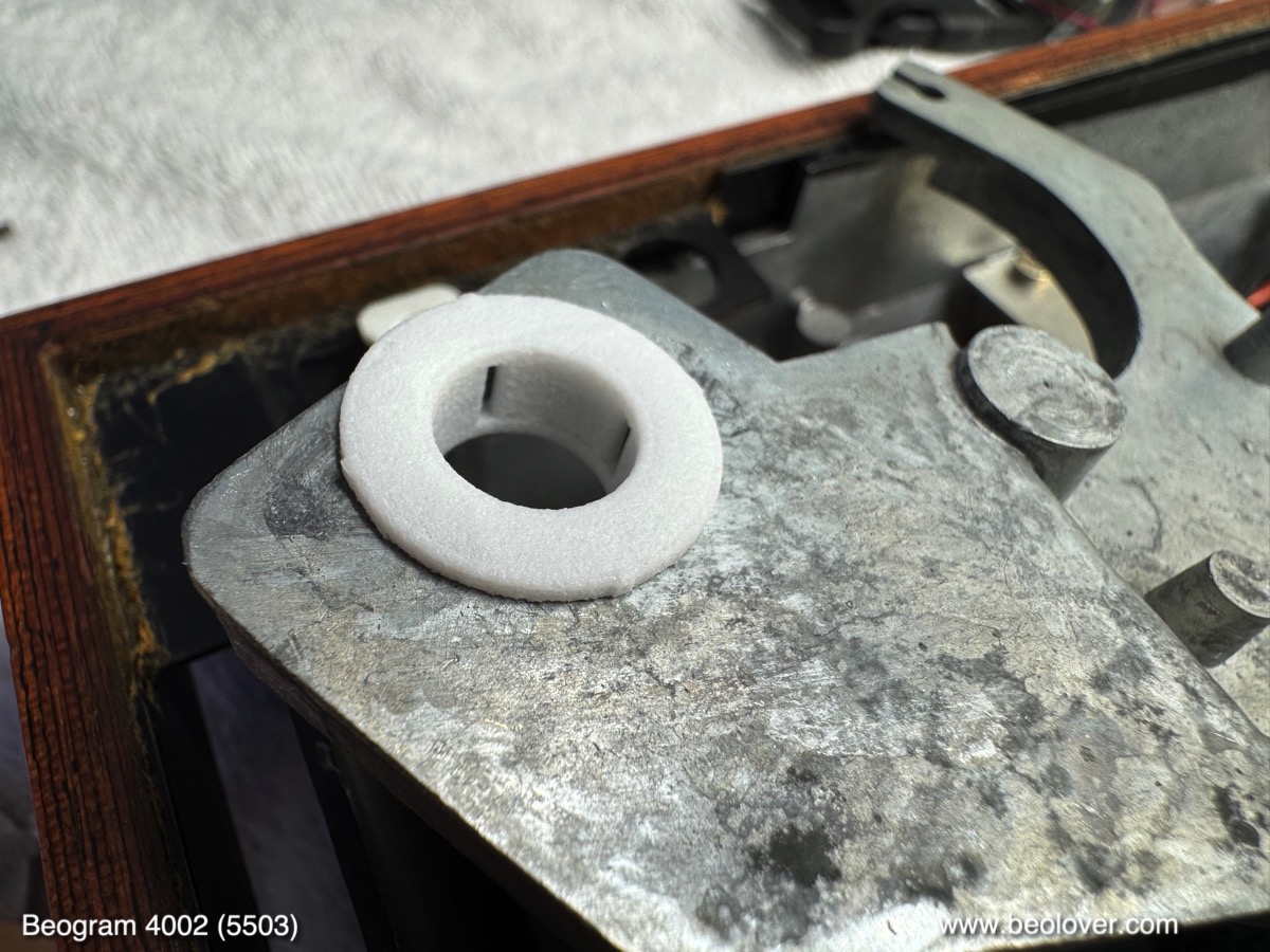
A number of strewn around orange plastic fragments indicated degraded transport lock bushings:
These will be replaced with new Beolover replacements made from resilient Nylon.
On the positive side, this unit has an original rosewood plinth in nearly pristine condition with nice front corners:
The aluminum surfaces also are in almost pristine condition. Especially the platter is in excellent condition:
It is difficult to find perfect platters, especially the older heavier ones that come with the AC motor Beograms like this one.
For some reason people manage damaging platters at an alarming frequency. They are especially fragile since they have a surface coating that is easily damaged through ill-advised cleaning attempts with alcohol, harsh chemicals and/or abrasive cleaning pads or cloths. It is best sticking with a soft cloth and water and some mild hand-dishwashing detergent and accept any damages that cannot be removed in this way. It is easy to make things much worse.

I removed the plates and platter for having a look below deck:
The unit seemed in original condition without major evidence of 'human creativity', which is always the best starting point for a restoration. It has the usual degraded plinth guidance washers:
Obviously this unit sat in a basement or attic for a while: Rodents had a go at the power and output cables. This shows the damage on the power cable:
I always wondered why rodents love eating cable insulation. Plastic does not seem to be a tasty snack! Why not go for a happy tasting nut instead?? We may never know!...;-). Luckily I have a bunch of original cables in good condition in stock that I extracted from parts units I came across in the past. So this is no showstopper either.

I plugged the unit in and pressed "ON". It came alive and sluggishly launched the carriage towards the LP set down point. It then ignored the set down point and came to a stop a few inches after that with the motor spinning against the very loose carriage belt. Too much friction due to hardened lubricants...
That it missed the set down is most likely related to a dead sensor arm bulb (the B&O logo at the end of the arm was dark). I pressed 'OFF' and helped the carriage to get moving back towards its home position.

In summary, this unit is a perfect starting point for a full restoration. The cosmetic issues can all be fixed and its life signs suggest a predictable restoration process. Stay tuned for my report on the restoration process. Once I am done it will be offered on my 'restored B&O for sale' page.


Tuesday, July 22, 2025

Beogram 4002 (5503): A New Arrival From Ontario - First Impressions (Exciting!!: The Main PCB Has a Burn Hole!)

A while ago I received a Beogram 4002 (Type 5503 with AC Platter Motor) from a customer in Ontario for restoration. This post discusses my initial assessment. I extracted the well-packaged Beogram from the Beolover shipping container and put it on my bench:

The hood is quite scratched up:
But it does not seem to have cracks in the hinge area and only minor damage on the inside. This means it could be polished back to a decent look. The better solution would be replacing it with a new reproduction hood from the dksoundparts store in Denmark. Their hoods are faithful reproductions and look crystal clear. Polished hoods always retain some degree of cloudiness.
This shows the deck after I removed the hood: 
It has nice aluminum surfaces and the platter is also in nice condition. It does have the usual use-smudges on the keypad:
Sadly, the coating on the keypads gets damaged when they are used. The acids and fats in the skin degrade the surface. Luckily, we are now able to restore such keypads by installing a brand new Beolover keypad. these keypads are faithful reproductions of the original ones, but are made with a modern coating that should be more resilient. See here for more details about this service.
The wood plinth is in pretty nice conditon with sharp front corners. Right
and left:
I removed the panels and the platter for having a look 'below deck':
The unit has seen some repair efforts already. The motor phase capacitor had been replaced at some point:
I will replace the entire capacitor setup as well as the power supply with the Beolover Efficient 22.8V Power Supply and Main Capacitors for Beogram 4002 (Types 550x). This upgrade will eliminate the chaotic wiring and also reduce the power consumption significantly, which will make the deck run less hot.
Other notable issues are the completely degraded plinth guidance washers:
A typical issue for this vintage Beogram. Luckily these washers can be replaced with a Beolover Plinth Guide Washer Set for Beogram 4000, 4002, and 4004. These reproductions of the original washers are made from long lasting nylon for smooth sliding.
More spectacularly, this Beogram has a burn hole in the main PCB:
This points towards a major failure at some point in the life of this Beogram. It will be interesting to see which part burned out.
This unit also has been already updated by added capacitors to the solder side of the board. These capacitors alleviate a potential issue with this design where a 45 RPM switchover sometimes occurs right after pressing ON:
After having seen the burn hole on the PCB I pressed ON with limited expectations. Surprisingly, the carriage started moving and the platter motor came on. The carriage also found the LP setdown point. All good signs! I guess this means the burn hole damage was patched after it happened...;-). 
In summary, I think this unit can probably be restored to like new appearance and performance.
Stay tuned for the next post describing my restoration process.


Thursday, April 10, 2025

Beogram 4002 (5503): Intermittent Tracking, Installation of New Carriage Motor and Restored Keypad and Update to Latest Beolover State-of-the-Art

I recently received a Beogram 4002 (5503) that I had restored in early 2020. After running for a while it came back in August 2023 with a fried H-Bridge. The H-Bridge is responsible for driving the DC carriage motor. It allows reversing the current direction even if there is only a single positive voltage rail in the system. It does that with transistors that act as switches to reverse the polarity on the motor leads. These transistors need to be able handling the motor current. If everything goes well, the current capacity of the transistors is safely above the current drawn by the motor in all operational situations.

Electric motors draw more current when they run under load since they run slower at the same applied voltage. The slower RPM causes the motor back-EMF (the self-induced voltage in the motor, which is opposed to the driving voltage) to be lower, so more of the applied voltage arrives at the motor coils, which in turn increases the current in the motor windings. This is a great feature of electrical motors since it means maximum torque at zero RPM, great for burning some rubber at a green light to impress ICE vehicle drivers (whose torque-to-RPM ratio is reverse: Minimum torque when the car is at rest and maximum torque when it is at speed...;-).

But this also means that if a mechanical system that is driven by an electrical motor develops more friction over time due to hardened lubricants or dry motor bearings, the motor will draw more current than when the system was new.

I finally came to realize over the years that this may be the root cause for H-bridge failures in Beogram 400x. The H-bridge transistors are able to handle currents of 1 Amp max. And when everything is according to spec fast forward or reverse typically draws about 0.1-0.2 Amps. 5x is a decent safety margin. But when there is additional friction, the current can get dangerously close to 1 Amp or even exceed it. This is evident from the often found blackened PCB surfaces under failed H-bridge transistors.

The main reasons for this issue are the carriage motor itself and hardened lubricants in the carriage translation mechanism. The latter can easily be addressed by cleaning and re-lubricating, but in the case of the motor replacement is necessary. In difference to the later DC platter motors, these motors cannot be rebuilt easily. This was the reason I designed a replacement motor that draws less current than the original motors at a similar torque. Due to its modern design it also creates less vibrations and noise compared to the original motors. This post describes an evaluation of my design.

So I am not really surprised anymore that this Beogram came back again with carriage drive issues considering the earlier H-bridge issues. This time it sometimes stopped tracking. An indication that the carriage motor developed even more friction in its bearings since the last visit. 

Therefore, the first step was to replace the carriage motor with the new Beolover Carriage Motor for Beogram 4000, 4002, and 4004:

This shows the original motor in place:

I extracted it and opened the enclosure up:
Then I installed a new Beolover motor:
It is a bit shorter, which permits feeding the leads through the hole in the enclosure bottom for convenient routing. This shows the motor in place:
After the motor I also replaced the H-bridge power transistors, which were potentially compromised due to the too high current draw of the carriage motor. This shows the H-bridge as I left it in 2020:
I removed the four transistors:
1TR25 definitely got a bit hot as suggested by the browned PCB surface under it. This transistor participates in driving the carriage left towards the home position. This is probably the most stressed one since every time the carriage returns home it goes full speed for maybe 20 sec giving this transistor some time to heat up.
I installed a new set of transistors and then it was time to update the RPM panel backlight LEDs. I had replaced the bulbs in 2020, but back then I still used homemade boards featuring red/green LEDs tuned to yield an incandescent sheen. This shows the bulb covers of the RPM panel:
I removed the covers, which revealed the LED boards I had installed:
I removed these PCBs. This shows the old design together with my current solution:
The new boards solder directly to the solder points of the original light bulbs. They essentially act as an extension of the circuit board. This shows them installed:
They give the RPM adjustment scales a nice incandescent-like backlight:
My customer also wanted me to update the main capacitor setup and the wasteful linear regulator based 22.8V power supply. This shows my work of 2020, when I still used big radially leaded capacitor cans similar to the original setup:
This board solders directly to the existing leads that previously connected to the big capacitors. The board also replaces 0TR1 (to the right of the platter motor in the picture) that regulates the 22.8V rail in the original setup. My board uses a modern buck converter to create the system voltage from the rectified DC coming from the transformer, which is much less wasteful and results in a cooler running and less energy using Beogram.
Looking at my notes from 2020, I saw that I did not de-magnetize the solenoid plungers yet as a standard restoration item. These plungers often get magnetized to various degrees, which can result in sluggish arm lifting. During auto-return at the end of a record this can cause the tip to drag over the platter for some distance before it finally lifts up when the spring overcomes the magnetic attraction. For demagnetizing the plunger the solenoid has to be extracted and then the plunger unscrewed from the angled bolt that connects the solenoid lever. This shows the solenoid in place:
Indeed the extracted plunger was magnetic. I usually test this with a ferrous set screw. If the plunger attracts the screw it needs demagnetizing:
After using my tape head demagnetizer on it a bit the screw was not attracted to the plunger anymore, 
so I put everything back together.
I also found that the sensor arm LED replacement was still one of my early versions based on a home etched flex PCB that I folded into the small bulb compartment:
This shows the extracted old part in comparison with my current approach, based on a small PCB and a 3D printed alignment aid:
This shows it in action. It uses a warm white LED that has enough red photons for lighting up the B&O logo in a realistic warm red:
Next came the replacement of my original early design transport lock bushings. The one on the left in the picture below shows my original design, which has a much wider wall thickness. Over time I came to realize that it makes the adjustment of the sub-chassis much easier if there is a bit more room around the lock bolts. So I re-designed the bushings with thinner walls (shown on the right): 
An added nice benefit of these new bushings is that the sub-chassis can move much more before it hits the lock bolts. This gives gives it a much more supple feel when the platter is touched and just freely swings. This shows one of the bushings installed:
Their two halves are simply pushed in from the top and bottom, which makes installation very easy. This shows the liberated chassis during the installation of the bushings:

The final update was to replace the smudged keypad with a new Beolover replacement. This shows the original keypad:
Most of the 4002 and 4004 keypads develop such use traces over time. First it starts with such 'smudges', basically polished areas caused by friction with the fingers when operating the Beogram. As time goes on the coating wears fully through. Luckily co-Beolover Beomazed recently succeeded after a long time of trial and error with reproducing the keypad plates. His plates are completely new and carry a modern resilient coating that promises to last for a while. This shows the restored keypad:

Absolutely stunning. They really look like the original pads! Read here how he does it!
If you are interested in getting your keypad restored, please visit here.
I installed the renewed pad in the Beogram. This is how this beauty looks now!:
And then it was finally time to enjoy this fully Beolover state-of-the-art restored Beogram with one of my favorite records by Chico Hamilton: "chic, chic, chico", which he recorded in 1965 on Impulse! I have the stereo version AS-82. He looks really chic on this one!...;-). A stunning record that has just the right amount of 'avant-garde edginess' as one would expect from an Impulse! record! A great match for this beautiful Beogram 4002!:
I will now play a few more records on this deck and then it will be time to send it back to its owner in California!