Featured Post

Beolover SyncDrive: DC Platter Motor Replacement for Beogram 4002 and 4004 (Type 551x and 552x)

Late Beogram 4002 and the 4004 (Types 551x and 552x), which have DC platter motors instead of the earlier synchronous AC motors usually suff...

Showing posts with label 2060008. Show all posts

Wednesday, March 13, 2019

Beomaster 1900 Type 2904: Testing and wrapping up the project

This Beomaster 1900 receiver is finally ready to perform the job it was intended for.

I don't have as many options for connecting up my audio analyzer probes inside the Beomaster 1900 like I did on the Beomaster 8000 but I am able to perform the main tests I wanted to do which are a total harmonic distortion (THD) test at maximum output into my dummy 8Ω speaker load using a 1KHz sine wave source signal and a frequency response test.

Here is my newest testing apparatus, two new dummy speaker loads.


My previous dummy speaker loads were made with a single 8Ω resistor for each channel. The new test loads have a 4Ω resistor in series with two 2Ω resistors and a 0.08Ω sensing resistor.  This gives me more connection points for measurement probes to use in combination with the audio analzyer attenuators...so I can setup the measured signal at a level most suited for the analyzer.

I still expect to primarily connect up the analyzer probes differentially across the 0.08Ω sensing resistor as shown in the picture.

The DMM probes are across the full 8Ω load so I can monitor what the amplifier output level is actually at. This is especially useful on the Beomaster 1900 where you really don't get a numeric value for the volume. I find it difficult to visually tell if I have the same volume level when using the touch controls unless I can see the result on a DMM.

The connection to the QuantAsylum QA401 audio analyzer from the 0.08Ω sensing resistor is via the two differential BNC connectors.


The first tests I ran were for the total harmonic distortion (THD).  The Beomaster 1900 - Type 2904 service manual states the maximum THD should measure less than 0.2%.  I take that to mean at full power output (20W into an 8Ω speaker load).

As mentioned in other Beomaster amplifier tests here on the Beolover Blog, we can't duplicate the test setup exactly as Bang & Olufsen did when the Beomaster 1900 was manufactured. However, we should come close and we collect these new test results to use as a reference for other restoration projects of the same Beomaster models....so keep in mind that this testing is an ongoing learning experience.

Here are the Beomaster 1900 left and right channel THD measurements. The QA401 audio analyzer generated the 1KHz sine wave test signal to the Beomaster 1900 Tape input. I adjusted the volume on the Beomaster as best I could to just under 12.7Vrms (which is 20W across 8Ω).  The Beomaster 1900 is a little tricky to dial in a specific volume level value (like 12.7Vrms).  My measurements ended up being more in the range of 11.7Vrms to 12Vrms. 


The right channel measured 0.13% THD which is comfortably below the spec value of 0.2%. 
I was happy with that but then surprised when the left channel measured 0.034%. 


Both channels are obviously in spec but not having measured this Beomaster 1900 before I have no reference data whether this is typical.

To be safe I decided I would run through and recheck the no-load current settings of the output amplifiers. Perhaps that adjustment had changed.

This meant removing the Beomaster 1900 bottom cover and the tone control/FM tuning cover in order to access the measurement and adjustment points. The probe connections across the two emitter resistors for the no-load current adjustment are too difficult to reach on the component side of the board so I connect from underneath.


The adjustment trimmers are also a little hard to reach.


I ended up spending a couple of hours on the readjustments.  Initially I checked them with the amplifier cold. Both channels measured up close to 14mV across the emitter resistors (R256 and R356). Eventually they settled to the low 11mV range. I adjusted them both back to 12mV then reconnected the dummy speaker loads to drive the outputs for a while up to 20W across the 8Ω loads again. After that I lowered the volume level to zero and removed the speaker loads again to check the no-load current measurements. Since the amplifier was warmed up it took a while for the voltages to settle back down. Both channels dropped to about 11.5mV.  I adjusted them back to 12mV one more time and repeated the test. 

This time the no-load adjustment check measured close to 12mV on each channel's emitter resistor.


After all of that I remeasured the THD for 1KHz at 20W and...got the same results as before.
Right channel THD is 0.13% and the left channel THD is 0.03%.  I did try measuring the THD for both channels at a lower volume (10W).  The right channel THD dropped to 0.09% but the left channel remained at 0.03%. 

It would seem like a lot of effort for no gain but I feel better knowing that the output amplifier is adjusted as good as I can get it.

In addition, while the two channels are not identical in their THD test, both channels do meet the Beomaster 1900 spec value. I am satisfied with the THD result now.

The last performance measurement I wanted to do is a frequency response test. The Beomaster 1900 spec for frequency response on the Tape input is 20Hz to 20KHz ±1.5dB.

The frequency response measurement is another test that is an ongoing development for me with my current test equipment set up. For this first time Beomaster 1900 frequency response check I decided to try the QA401 new frequency response plotting feature. Like the THD tests I used the QA401 differential input probes across the 0.08Ω sensing resistor in my dummy speaker load.

The test automatically sweeps test frequencies from a selected range and plots the amplitude of the output signal. I selected a sweep from 15Hz to 40KHz.

Here are my results.


The frequency plot for both channels is within the ±1.5dB specified by the Beomaster 1900 spec from 20Hz to 20KHz so I am happy with that. I marked the 1KHz test signal amplitude as the zero reference to check the ±1.5dB amplitude to. I tried to lock the volume level to the same position for both channel frequency response test but I ended up with the left channel running at a slightly higher level.

Now for a final play test and this Beomaster 1900 should be ready to return home.
I decided to connect up this receiver to my spare Beosystem 8000 where the Beomaster 8000 project recently vacated from. I was interested to see how a Beomaster 1900 would do driving a pair of Beovox M100.2 speakers.


Not a problem for the "little" Beomaster 1900. 20W of maximum power is plenty for a pair of Beovox M100.2 speakers in a small listening room (12 foot x 12 foot).

The final performance evaluation is now my own ears enjoying music controlled through this great little amplifier from the seventies.

Monday, March 4, 2019

Beomaster 1900 Type 2904: Cleaning, polishing and reassembly

For about a week since the last post this Beomaster 1900 has been sitting on the workbench playing music for hours on end. No problems surfaced during that time so with the new parts broken in I am ready to reassemble the Beomaster before going into the final stretch of testing.

The trickiest part of the reassembly has to be the touch control panel.
The copper, spring leads for the touch controls must fit onto corresponding posts on the Beomaster 1900 circuit boards. A trick Martin Olsen taught me was to install this panel with the Beomaster 1900 bottom cabinet plate still removed. That way you can inspect each touch control contact from underneath and use some tweezers or probe to maneuver the contacts into place.


I reinstalled the indicator masks for the bass, treble and balance slide controls at this time.
I also used some plastic cleaner and aluminum cleaner on the touch panel as I installed it.


The next piece to install is the other part of the top cover. The grooved section for the heatsinks and the access door hinge had a lot of dirt and grime from wherever this Beomaster was stored.


I cleaned it with mild cleaning solution and a couple of brushes to get into the channels.
The right side hinge of the access door was loose and came off so I reattached it with some epoxy.
Before reinstalling the base of the cabinet I gave the Beomaster a quick test to make sure all of the electrical connections were still good.


Finally I could install the cabinet base. This cabinet was missing all four of its feet so I used the replacement feet I recently got from Martin Olsen.


While the Beomaster 1900 was upside down I noticed that the Phono DIN jack is a 7-pin DIN connector.  There isn't anything wrong with that but the Beomaster 1900 will never utilize the number 6 and 7 pins of that connector. The Beomaster 2400 is the receiver with a remote control and can control Play/Stop functions of a Beogram 4004 via the 7-pin DIN. Except for the remote control the Beomaster 1900 and 2400 share the same circuit board so I guess Bang & Olufsen just started installing the same source connectors on both receiver models.


The Beomaster 1900 is all assembled again so I turned it over and started another play test session.


This week I will connect it up to my audio analyzer and make some measurements. After that I will hook it up to a Beogram and Beocord to round out the functional testing.

Monday, February 25, 2019

Beomaster 1900 Type 2904: Cosmetic repair - side trim replacements

Before reassembling this Beomaster 1900 for testing I took a little time to replace the two "wood" side trim pieces. Actually, the trim pieces on these Beomaster 1900 units are a plastic base to which a thin rosewood veneer is applied.

The rosewood veneer on this Beomaster has started to peel and has some unsightly damage. I had originally hoped to save it but there is just too much deterioration of the veneer.


There are areas where the rosewood is missing so just re-glueing what is left wouldn't do much good in my opinion. The plastic base pieces can be saved and reused in the future. It probably wouldn't be too difficult to find, cut and glue new veneer onto the plastic bases...but I'll save that for a future project.

On this project I am taking the two side trim pieces off a parts Beomaster 1900. It works out well for this project because my parts unit is missing its front trim veneer but the side trim pieces are perfectly intact.

Here they are installed on this Beomaster 1900.


Sunday, February 24, 2019

Beomaster 1900 Type 2904: Service manual adjustments and first play

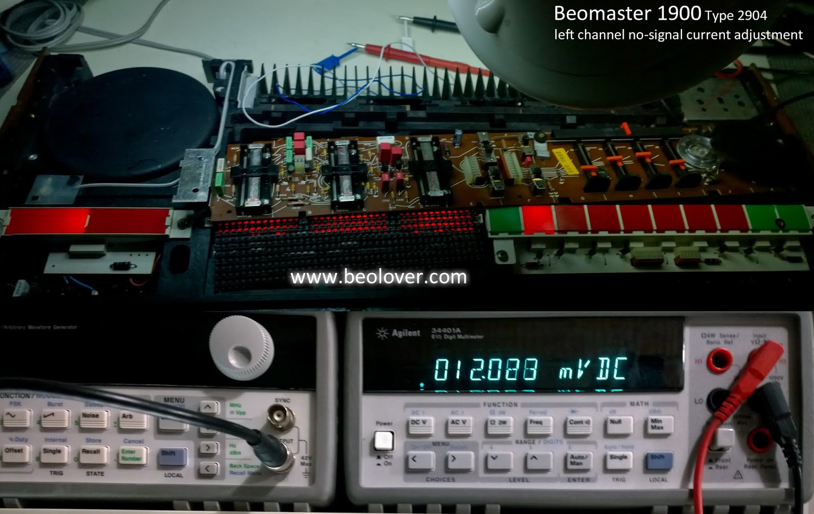
After the indicator lamp replacement I set up the Beomaster 1900 for the no-signal current adjustments of the amplifier.

The adjustment procedure is to measure the voltage across the left and right emitter resistors (R256/R356 respectively) and adjust the left and right trimmers (R249/R349 respectively) so the voltages read 12mVDC.

The emitter resistors are in a bad location to connect up probes from the top of the main board so I connect the measurement probes on the underside (trace side).

There is just enough room to get to the trimmers on the component side for the adjustment.

Here is the left channel


The measurement and adjustment are to be made when the amplifier is cold and first turned on. The volume level should be at its minimum and no speakers should be connected.
Here is the measurement for the left channel emitter resistor


Here is the right channel


Another service manual check and adjustment is for the FM1 tuning voltage.
This test measures across the tuning board 4R1 (4TP1) while setting the Beomaster 1900 to FM1 and the FM1 tuning slider to 88 MHz.  The 4R2 trimmer is adjusted so 4.7 VDC is measured at 4TP1/ground.


The same type of test is performed for FM5. The measurement is again measured across 4TP1 to ground but the FM5 is the selected FM source. The FM5 tuning wheel is turned to 88 MHz then the 4R8 trimmer is adjusted to 4.8 VDC at 4TP1.


Once these adjustments were made I connected up my FM antenna and my workshop Beovox S55 speakers.

This Beomaster 1900 is playing music again and sounding quite nice.


I let the Beomaster play overnight to burn in the new components.  Later today I will start reassembly of the Beomaster then run some performance tests.


Saturday, February 23, 2019

Beomaster 1900 Type 2904: Lighting it up

In the last post of this Beomaster 1900 restoration I was briefly concerned when I powered the Beomaster up and there was no Standby lamp. When I selected one of the sources I could hear the Beomaster power relay engage but most of the lamps were not functioning.

I breathed easier when the power supply tests all checked out and I verified that the lamps all had correct voltages to be illuminated. So it just that the majority of the lamps were shot.

My fix for the lamps is to replace the two volume level indicator lamps, the two FM tuning lamps and the single FM stereo indicator lamp with new incandescent bulbs that I acquired from Martin Olsen of Beoparts. The bass, treble, balance and source selection indicator lamps are all replaced with LED modules that I build (just a 3/4 inch, white, through-hole LED with a 1KΩ series resistor).

I like using LEDs on the bass, treble and balance indicators because the LED lamps run a lot cooler than their incandescent counterparts. That makes it easier on the plastic mask material for those displays. On the source indicators the heat factor is not really an issue but I prefer to use the LED replacements there because they are less delicate and likely to last longer.  All of my LED replacement modules are built to just plug in the board the same as an incandescent bulb with the exception that polarity must be taken into account with the LEDs. Switching back to an incandescent lamp is just a matter of desoldering the LED assembly and soldering an incandescent lamp back in.

Finally there is the Standby lamp which is already a red LED. However the Standby lamp in this Beomaster has failed so it will get a new red LED lamp.

Regarding the five lamps that I am keeping incandescent type bulbs...the reason for that is because those lamps are part of their respective Beomaster circuit function. Changing those to an LED would negatively impact the circuit function.

Here is the indicator board with the most lamps to replace...the FM tuning and source selection indicator board.


Here is the board with new indicator lamps. This picture shows the Beomaster 1900 in Standby mode and the new red indicator LED is working.


I ran through all of the source selection options and all of the new LED indicators work. So do the two new incandescent lamps for the FM tuning.  I didn't check the stereo indicator lamp yet.  I will get to that one when I start bench testing the receiver functions of this Beomaster and an FM antenna is connected.


Here is the bass, treble and balance indicator board as I received it. All three lamps were not working although +15 VDC was measured across them.


Here is the bass, treble and balance indicator board with the LED replacements. I used two LED lamps on each indicator for a better light coverage.


There are two Beomaster 1900 volume level lamps on the volume indicator board. One of the two was burned out.  Here is the board with two new incandescent lamps.


Now the display indicator lamps are all working again. I can move on to adjusting the no-load current setting on the output amplifier stage then see how this receiver sounds playing music.

Friday, February 22, 2019

Beomaster 1900 Type 2904: Initial Power Supply Voltage Checks

This week I checked out the recapped Beomaster 1900 power supply. This is the first time to power the receiver on since the restoration work began.

Plugging the Beomaster 1900 in did not illuminate the LED Standby indicator. That is always a little scary but when I touched one of the program selection touch terminals the Beomaster powered up.


So I do have power. The picture above shows there are problems with the lamps though. The illumination lamps for the bass, treble and balance slider controls are not working. I tried some other source select functions and most of the lamps are out as well.

I needed to actually measure the Beomaster 1900 power supply voltages to verify the problem is with burned out lamps.

Starting with the ±31 VDC rail voltages I checked the two big reservoir capacitors.


Those voltages are present and look healthy.
On to the +15VDC power supply check. It's reservoir capacitor and regulator output look good (measured at TP16).


Another place to check for +15VDC is the TP15 test point.


There is also the -12VDC, TP14 test point.


Finally, a few checks of the indicator lamps that are not illuminating.


The lamps have voltage so they must be burned out.

Today I will replace lamps then revisit the voltages. Once those tests pass I will adjust the output amplifier idle current and start on some functional tests.


Sunday, February 17, 2019

Beomaster 1900 Type 2904: Capacitor Replacement Part 2 and Slider Control Repair

All of the electrolytic and tantalum capacitor replacement tasks are complete now on this Beomaster 1900 project.

The last board was the tone control and FM tuning board.

There are are only eight capacitors to replace on that board. Here are two before pictures.


...and here are the after pictures. Very straight forward.


The larger task on this board is the repair of the three slider controls (bass, treble and balance).
It is very common for these controls to fail on the Beomaster 1900. The failure is mechanical and involves the plastic slide that holds the left and right channel contacts for the respective control.


A small plastic tab that holds the metal contact in place breaks and the contact becomes free to move around. This results in faulty or no sound in one or both channels.

I noticed at least one loose contact when I did my initial assessment of the Beomaster. To be sure of the condition of all the sliders they must be disassembled and checked.

It is a good idea to label the slide controls as they are removed from the board.


Two small, metal tabs on the end of the control must be bent straight so the metal clamp/holder can release and allow the contact slide mechanism to be removed.

Here are all three sliders disassembled. I found three with broken contact mounting tabs.


The repair for this problem is best made using a repair kit from Martin Olsen. Martin makes a number of  accurate replacement kits for various vintage Bang & Olufsen components that he sells on his Beoparts website.

In this case the kit consists of three replacement (plastic) slider control parts plus some useful instructions.


I cleaned the metal contacts and slider areas with Deoxit (cleaner and fader lube). Then I reassembled the slider controls.


Next up are the lamp replacement tasks.