Featured Post

Beolover SyncDrive: DC Platter Motor Replacement for Beogram 4002 and 4004 (Type 551x and 552x)

Late Beogram 4002 and the 4004 (Types 551x and 552x), which have DC platter motors instead of the earlier synchronous AC motors usually suff...

Showing posts with label encapsulated. Show all posts

Wednesday, November 16, 2016

Beomaster 8000: Step Seven - Replacement of the Speaker Switches with Modern Encapsulated Units and Laser Cut Adapter Plates

The final 'standard restoration task' for a Beomaster 8000 is to replace the speaker switches. My own personal statistics are that in about 50% of all Beomaster 8000s these switches will go bad in the near future if they are used regularly, like for headphone listening etc...They are usually corroded on the inside and frequently when a Beomaster is used again after a long period of storage, they break after a few uses and then the outputs are no longer connected to the speaker jacks. This shows the speaker switches flipped out of their 'compartments' for accessing the solder points:

Note the brown PCB-like base plates that hold the contacts...this switch style has long gone out of fashion in favor of fully encapsulated modern designs that are capable of millions of switchings before they need to be replaced. Unfortunately, these modern switches do not have this base board anymore, and hence they do not fit into the compartments under the heatsink cover. I designed laser-cut adapter plates that mimic the original base plates while snugly fitting the footprint of the modern switches:
This shows them after soldering them in:
And situated in their compartments:
All good now in switch land!

Unfortunately, when I gave this Beomaster a subsequent testing of all functions, I realized that the phono jack in the contact box was broken out and also disconnected. Very beo-unlovely! The next post will report about my repair process of these DIN7 jacks.


Thursday, February 25, 2016

Beogram 4002 (5513): Rebuilding the Output Board, Installation of a Grounding Switch and Repair of the Keypad

The Beogram 4002 (5513) that I am rebuilding right now is nearing completion. Today, I did the output PCB (#8) and I repaired the keypad which had a loose key stop.
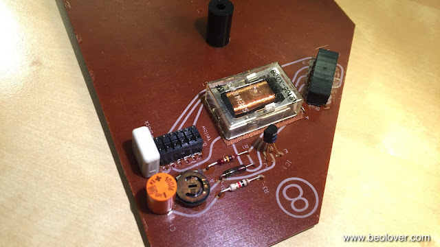
This shows PCB #8 in original condition:
I like to replace the output relay, since they often get stuck on one or both channels as they age. Fortunately, it is the same relay that is used for switching the platter RPM and so my replacement relay boards fit here, too:
These parts are available to other enthusiasts, just send me an email.
This shows the relay and the capacitor replaced:
The red switch allows to connect the system and the signal grounds. This can help if there are hum issues due to improper connections within the amplifier or the cable (usually when RCA adapters are used that do not breakout the system ground).

Before I put the board back in, I also fixed the keypad. It had a loose key stop that caused one of the keys to pop up above the pad surface:
This shows the STOP key from the back with the loose stop:
I glued the stop back on and also reattached the loose pad strips on the sides:
This shows the end result of this repair:
Beautiful! On to adjusting the chassis and the platter.


Wednesday, February 17, 2016

Beogram 4002 (5513): Rebuilding the Output Board and Adding a Grounding Switch

I also rebuilt the output board of the Beogram 4002 that I am restoring right now while I had the keypad out for cleaning the contacts. The output relay is a frequent source of low or no volume on one or both channels and so it is a great idea to replace it with a modern Japanese made encapsulated relay, which will last for decades. This shows the output board in its original configuration:
The old Siemens relay was replaced with this custom designed SMD relay assembly:
This assembly directly fits into the solder points of the original relay. It is available to other enthusiasts. Just send me an email. Here is an impression of the rebuilt board:
I also replaced the time delay capacitor for the relay with a 105C grade Japanese type. The switch that sits in front of the output jack can connect signal and system grounds if necessary for hum suppression. This can be helpful, especially if RCA plugs are configured and there is no separate grounding pin on the amplifier.