Featured Post

Beolover SyncDrive: DC Platter Motor Replacement for Beogram 4002 and 4004 (Type 551x and 552x)

Late Beogram 4002 and the 4004 (Types 551x and 552x), which have DC platter motors instead of the earlier synchronous AC motors usually suff...

Showing posts with label 104EMBG4002. Show all posts

Friday, June 3, 2016

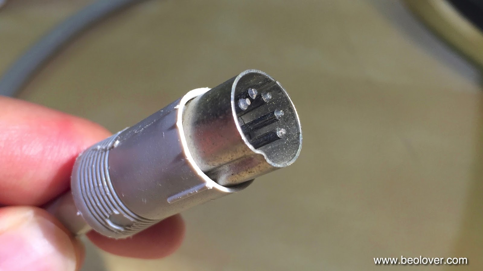
Beogram 4002 (5503): Installation of a New All-Metal DIN5 Plug with Gold Plated Contacts

In my opinion no Beogram 4002 restoration is complete without replacing the usually corroded original output plug(s) with modern all metal units with gold plated terminals. Those precious analog signals deserve only the best! Here are a few impressions of the DIN5 replacement that I just did for the Beogram 4002 (5503) that I am finishing up:

This shows the original DIN5 plug:
This shows the soldering job 'under the hood':
A proper DIN5 installation requires that the shield is separated from the signal ground and that the insulation of the signal leads extends to the solder terminals. All this can be a bit fiddly due to the small space and thin leads one works on. 
This shows the new plug closed up:
Pretty, isn't it?? This is Beolove!


Thursday, June 2, 2016

Beogram 4002 (5503): Keyboard Repair - Detached Backstops

After restoring the hood of the AC motor Beogram 4002 (5503) another cosmetic item on the list was the reattachment of the broken off backstops of the keypad. This shows the situation that I encountered:
Some of the keys were sticking out. Also the keys were working somewhat unreliably. Often one had to press them repeatedly to activate a function. Removal of the keypad and removal of the PCB revealed this situation:
Several of the plastic backstops had come loose and a previous user tried to re-attach them with double sided tape. Due to the thickness of the tape some of the keys appeard 'elevated' on the top side of the keypad

A bit of wiggling on the backstops that were still attached easily liberated them. The challenge was to glue them back in place in a precisely oriented and with the right pitch. I elected to design 3D printed alignment tools that would hold the backstops in place for glueing them in:
The tools can hold the backstops in the proper orientation and pitch:
Once the backstops are inserted onto the tools, they can be glued back under the keys:
And so the keypad looks good again:
On to replacing the old corroded DIN5 plug with a new one!


Saturday, April 2, 2016

Beogram 4002 (5503): Hood Restoration

I polished the hood of the Beogram 4002 (5503) that I have on my bench right now. It also had the usual age conform scratches and chafed areas and so needed a good sanding and polishing back to translucency. Here is an impression of the original state:
The first step as in most cases was sanding with 220 grit paper:
Then it was time to polish it back to a clear state with Micro-Mesh polishing cloth. At the end it looks   clear and happy again:
The job was finished by inserting new rubber bumpers made from cuts of a 2 mm O-ring. This shows one of the original broken off bumpers:
I used a 2 mm drill bit to get the old rubber out and then I glued the O-ring sections in:
After the glue hardened I cut them to size that the hood would sit level on the plinth:
So far so good...the remaining task is to restore the keypad.


Friday, February 12, 2016

Beogram 4002 (5503): Replacing the Incandescent Light Bulbs in the RPM Indicators with SMD LED Boards

The 550x Type Beogram 4002s have a remarkable feature: When you plug them in, the 33 RPM scale light is glowing a bit, even without pressing start. Here is a picture of the RPM panel in this condition. In the gap between the light shield and the RPM scales housing you can see the bulb filament glowing.

This behavior is an indication that the 550x models have a different way to switch the platter speed. The original Beogram 4000 uses a relay to switch between the two 33 and 45 RPM time constants for the oscillator. The later 4002 551x and 552x DC motor models also use a relay to accomplish this task for their feedback circuit. However, the earlier AC motor 4002 types (550x) switch the RPM electronically. This is immediately evident  due to the absent relay click when the speed is changed on these models. The RPM changes silently. This is the relevant portion of the circuit:
This is how it works: TR5 and TR6 control whether the Wien oscillator oscillates at the proper frequency for 33 or 45 RPM. This is done by coupling either the 2R1 or the 2R2 connected passive elements into the oscillator feedback. TR5 and TR6 themselves are controlled by the flip-flop like circuit formed by TR3 and TR4. Each of their bases are connected to the collectors of their counterpart via a 8.2k resistor. A 3.3nF capacitance across each transistor's base and collector provides a time delay to enable a flip flop action. Whenever the 33 or 45 switch is pressed the base of the opposite transistor is briefly shorted to ground turning off the transistor. This causes a high potential at the collector at this transistor which via the 8.2k resistor pulls up the base of the other transistor, turning it on. That way, two states can be induced where either TR3 or TR4 is on but never both. Hence the flip flop action. Additionally, 45 can be turned on via TR2 whose base can also be pulled up via the carriage position detector circuit. 
The issue with this circuit is that there is still a significant (several mA) current in the bulb that is off to drive the base of the opposite transistor, and that causes the 33 RPM bulb to be slightly glowing even without 33 RPM on.
While with light bulbs this current results only in a fairly weak light emission (which apparently was accepted as o.k. by the B&O designers) when the bulbs are simply replaced with LEDs and a current limiting resistors as I do it in the DC motor 4002 Beograms, the result is that the LEDs are always on and quite brightly so. And of course this cannot be tolerated.

This meant I had to redesign the SMD LED boards for the 550x types. I solved the issue by introducing a voltage divider that makes sure that the voltage across the LEDs is small enough to ensure that they are dark while driving the base of the 'opposite' RPM transistor. Here is an impression of the boards:

The voltage divider is on the left side of the boards while the current limiting resistors are on the right side. This picture shows the board in on-state:
Once this was accomplished the installation is plug and play, very similar to what I show in my video about installing the boards in 4002 551x/552x types. This video shows how to install the LED boards. These parts are available to other enthusiasts. Just send me an email.
Here are a few pictures of the installation in this particular unit. This shows the original setup (the 33RPM bulb is already removed)
This picture shows the LED boards installed:
and with covers replaced:
The original melted 33 RPM cover is shown on the left. This Beogram came with a spare cover, which I installed. The LEDs run much cooler, i.e. there will not be any melting and browning of the plastic anymore. At this point I though I was done, but not so:
A test of the LEDs revealed that the strange light pattern that I initially noticed in the 33 RPM indicator compartment was still there. I had hoped this was somehow related to a misaligned light bulb, but this was obviously more serious. I decided to open up the indicator housing to have a closer look. After I removed the retaining washers (one has to essentially destroy them to get in there) I found this:
The left side is the 33 RPM scale indicator. Obviously the white reflector became wavy over time due to the heat load of the bulb, which caused a partial obstruction of the injected light, hence a wavy intensity pattern is observed.
I solved this issue by removing the wavy plastic foil and installing a new strip of white electrical tape:
Then I reassembled the housing using new 3 mm circlips and nylon washers:
A second functional test revealed a much more homogeneous illumination pattern:
A perfectly illuminated scale! This is Beolove!


Tuesday, February 9, 2016

Beogram 4002 (5503): Exchanging all Electrolytic Capacitors

After completing most mechanical adjustments it was time to restore the electronics of the Beogram 4002 (5503) that I am currently restoring. It is always a good idea to replace all electrolytic capacitors since their electrolytes often leak out or simply dry out. I use only 105C grade Japanese replacement capacitors to maximize the longevity of my restorations. In particular Tantalum based electrolytic need to go since they can die a fiery death if they short circuit due to electrolyte loss, which can leave black craters on the circuitboard. And that would be very un-Beolovely! So here we go:

My favorite part is always replacing the big old reservoir and motor coupling and phase capacitors. Here is an impression of the solder terminal side of the original setup.
The two capacitors on the right are the motor caps and the two bigger ones on the left are the reservoir capacitance of the 4002 power supply.
This shows the back side towards the AC motor:
Modern capacitors are smaller and this allows to clean up this set-up by using a custom designed 3D printed capacitor adapter that neatly holds the new capacitors:
This assembly is available to other enthusiasts. Just send me an email if you are interested.
Here is an impression after installing it:
and from the back:
The adapter fits snugly under the original holding strap, which holds the assembly firmly in place. And note the dedicated grooves that hold the wires orderly in place! Very Beolovely!!

On to the exchange of all capacitors on the main board. This shows the original set-up. The orange cans are often cracked or leaky. The small orange dots are the Tantalum capacitors:
There are also two Tantalum caps on the solder side of this board:
This shows the board after replacing all the caps:
and on the solder side:
There are a couple of electrolytic caps on the secondary boards of the 4002 (5503) such as this cap on the sensor board:
Of course it also had to go:
there is one more on the output board that is located under the keypad. I will get to that one once I exchange the RPM indicator light bulbs with custom designed SMD LED boards. For that I will have to pop out the RPM indicator panel, which in turn will give me access to the bolt that holds the keypad down. Stay tuned!


Saturday, February 6, 2016

Beogram 4002 (5503): Adjustment of Sub-Chassis, Platter and Tonearm Weight and Limits

The final step of the restoration of the mechanical systems of the Beogram 4002 (5503) that I am currently rebuilding was to balance the sub-chassis, adjust the platter height and bring the tonearm up to specifications. The sub-chassis needs to be adjusted that it sits centered between the opened transport lock clamps for maximum range of free motion. Then the platter height and vertical alignment needs to be adjusted that it sits flush with the aluminum covers of the Beogram. Once this is done, the arm lowering limit can be set and the tracking weight can be calibrated to match the scale on the weight adjustment dial on the side of the arm weight housing.
Here is a picture of the platter after all the adjustments. It sits centered in and flush with the opening in the surrounding aluminum plate:
Then the arm lowering was adjusted that the stylus just misses the lower parts of the ribs on the platter. This is an important adjustment since it will save the cartridge if the arm is accidentally lowered without a record present in case of a sensor malfunction (the control system is not setup to detect a photosensor failure):
Then I replaced the flimsy circlip that holds the counterweight adjustment screw in place with a nut. This ensures that the tracking force calibration is still correct after shipping the unit. This shows the original setup:
And with the M3 nut installed:
Then I balanced the arm:
In case you would like to do these adjustments on your Beogram, there are two videos on my YouTube channel that show how to adjust the platter bearing and the subchassis (in a Beogram 4000, but the process is very similar in the 4002). There is also a video about the tracking force calibration process, and there is another video on my youTube channel that shows how to adjust the lowering limits. 
On to rebuilding the electronic parts of this Beogram!


Friday, February 5, 2016

Beogram 4002 (5503): New Cabinet Guiding Washers and Transport Lock Bushings

To conclude the adjustments and restoration of the mechanical systems of the Beogram 4002 (5503) that I am currently working on I first needed to install new transport lock bushings. Only if they are in place one can properly center the subclasses between the upper and lower lock limits. This Beogram already had lost the degraded bushings earlier and presented itself without any trace of their original existence. this photo shows the disassembled left transport lock:
A bushing should be present in the orifice on the sub-chassis arm on the right.
This picture shows the first step of the installation of my replacement bushings:
I designed in two parts that one can insert them without having to extract the sub-chassis from the Beogram enclosure. There is a video about installing new transport lock bushings in my Beogram 4002 playlist. The bushings can be ordered directly from my Shapeways store. This is the link to the part. You will need two per transport lock.
This shows the upper bushing half installed:
This shows the lock put together again with the new bushing. I did the same for the other two locks. Then, since I was at it, I also replaced the original cracked cabinet guiding washers with my replacement washers. They are now printed in nylon at Shapeways using the selective laser sintering process. This yields a much more precise part that also has much better mechanical stability than my initial stereolitography reproduction. Here is a picture of an original cracked plastic washer:
This shows the cracked washer together with its new replacement:
And installed:
There is a video about this procedure in my Beogram 4002 playlist. The bushings can be ordered directly from my Shapeways store. This is the direct link to the part. Now we are ready to adjust the sub-chassis and the platter height!