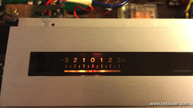
The 550x Type Beogram 4002s have a remarkable feature: When you plug them in, the 33 RPM scale light is glowing a bit, even without pressing start. Here is a picture of the RPM panel in this condition. In the gap between the light shield and the RPM scales housing you can see the bulb filament glowing.
This behavior is an indication that the 550x models have a different way to switch the platter speed. The original Beogram 4000 uses a relay to switch between the two 33 and 45 RPM time constants for the oscillator. The later 4002 551x and 552x DC motor models also use a relay to accomplish this task for their feedback circuit. However, the earlier AC motor 4002 types (550x) switch the RPM electronically. This is immediately evident due to the absent relay click when the speed is changed on these models. The RPM changes silently. This is the relevant portion of the circuit:
This is how it works: TR5 and TR6 control whether the Wien oscillator oscillates at the proper frequency for 33 or 45 RPM. This is done by coupling either the 2R1 or the 2R2 connected passive elements into the oscillator feedback. TR5 and TR6 themselves are controlled by the flip-flop like circuit formed by TR3 and TR4. Each of their bases are connected to the collectors of their counterpart via a 8.2k resistor. A 3.3nF capacitance across each transistor's base and collector provides a time delay to enable a flip flop action. Whenever the 33 or 45 switch is pressed the base of the opposite transistor is briefly shorted to ground turning off the transistor. This causes a high potential at the collector at this transistor which via the 8.2k resistor pulls up the base of the other transistor, turning it on. That way, two states can be induced where either TR3 or TR4 is on but never both. Hence the flip flop action. Additionally, 45 can be turned on via TR2 whose base can also be pulled up via the carriage position detector circuit.
The issue with this circuit is that there is still a significant (several mA) current in the bulb that is off to drive the base of the opposite transistor, and that causes the 33 RPM bulb to be slightly glowing even without 33 RPM on.
While with light bulbs this current results only in a fairly weak light emission (which apparently was accepted as o.k. by the B&O designers) when the bulbs are simply replaced with LEDs and a current limiting resistors as I do it in the DC motor 4002 Beograms, the result is that the LEDs are always on and quite brightly so. And of course this cannot be tolerated.
This meant I had to redesign the SMD LED boards for the 550x types. I solved the issue by introducing a voltage divider that makes sure that the voltage across the LEDs is small enough to ensure that they are dark while driving the base of the 'opposite' RPM transistor. Here is an impression of the boards:
The voltage divider is on the left side of the boards while the current limiting resistors are on the right side. This picture shows the board in on-state:
Once this was accomplished the installation is plug and play, very similar to what I show in my video about installing the boards in 4002 551x/552x types. This video shows how to install the LED boards. These parts are available to other enthusiasts. Just send me an email.
Here are a few pictures of the installation in this particular unit. This shows the original setup (the 33RPM bulb is already removed)
This picture shows the LED boards installed:
and with covers replaced:
The original melted 33 RPM cover is shown on the left. This Beogram came with a spare cover, which I installed. The LEDs run much cooler, i.e. there will not be any melting and browning of the plastic anymore. At this point I though I was done, but not so:
A test of the LEDs revealed that the strange light pattern that I initially noticed in the 33 RPM indicator compartment was still there. I had hoped this was somehow related to a misaligned light bulb, but this was obviously more serious. I decided to open up the indicator housing to have a closer look. After I removed the retaining washers (one has to essentially destroy them to get in there) I found this:
The left side is the 33 RPM scale indicator. Obviously the white reflector became wavy over time due to the heat load of the bulb, which caused a partial obstruction of the injected light, hence a wavy intensity pattern is observed.
I solved this issue by removing the wavy plastic foil and installing a new strip of white electrical tape:
Then I reassembled the housing using new 3 mm circlips and nylon washers:
A second functional test revealed a much more homogeneous illumination pattern:
A perfectly illuminated scale! This is Beolove!


No comments:
Post a Comment
Comments and suggestions are welcome!