Featured Post

Beolover SyncDrive: DC Platter Motor Replacement for Beogram 4002 and 4004 (Type 551x and 552x)

Late Beogram 4002 and the 4004 (Types 551x and 552x), which have DC platter motors instead of the earlier synchronous AC motors usually suff...

Showing posts with label RPM indicator. Show all posts

Saturday, December 29, 2018

Beogram 4004 Type 5526: Second Beogram 4004 from Texas almost ready for record play

In this update I have the second Beogram 4004 from Texas reassembled and nearing the point of playing records again.

I completed the last few component restoration tasks.

First there was the RPM indicator panel update to the Beolover RPM indicator modules. Those are custom plug 'n play LED lamps for the RPM panel. Platter motor stability tests with the LED RPM lamps show improved motor speed stability so when we restore a Beogram 400x with a rebuilt platter motor we always replace the RPM indicator lamps and the RPM relay on the controller board.


Here are the Beolover RPM indicator modules installed.


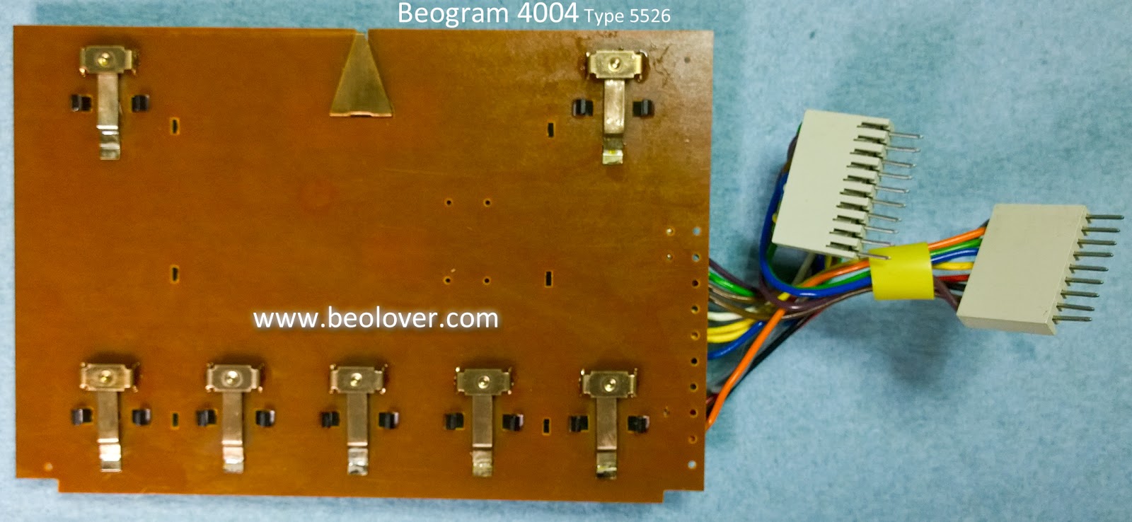
The keypad button contacts usually have oxidation that needs cleaning up.


The contacts on this one aren't too bad but while I have the keypad opened up I cleaned it with a fiberglass brush and Deoxit.


Now the components can be reassembled in the Beogram cabinet.

For the floating chassis I installed the Beolover 3D printed transport lock bushings.


With the bushings in place I prepared the transport lockdown screw assemblies. I will just show one as the other two are the same.


The upper and lower locking nuts were installed at the very ends of the threads to give maximum distance between them when the floating chassis is unlocked.

Next was the installation of the new reservoir capacitor. The new capacitor uses a Beolover 3D printed housing so it fits perfect in the cabinet.


Looks great.

Now for the reinstallation of the DC platter motor that Beolover restored for me at the beginning of December.


Now for the installation of the controller board, output board, keypad and RPM indicator panel.

This Beogram is ready to try a power on test.


Lights are on, the motors turn...those are good signs.

The next step is to measure the voltages and key sensor signals before starting the service manual checks.

Saturday, December 22, 2018

Beogram 4004 Type 5526: Finishing up the electrical work and testing the results

I left off the first of two Texas Beogram 4004 restorations with the main (controller) board and the output board recapped. There was another electrical task I wanted to complete before reinstalling and testing the results.

We like to (insist really) that the 33⅓ RPM and 45 RPM indicator lamps be replaced with Beolover LED replacement assemblies. The reason for that is those lamps are part of the platter speed control circuit and our speed stability testing shows these LED replacement modules provide a measurable improvement to the platter motor performance stability.

Here is the original RPM indicator module removed and the installation of the replacement Beolover RPM indicator assemblies.


All of the electrical pieces are ready so it is time to reassemble things back in the Beogram cabinet.

One of my earlier posts showed that the suspension locking bushings on this Beogram were deteriorated to the point of crumbling away. The next pictures show the installation of the Beolover 3D printed replacement bushings.


I am not fully reinstalling the circuit boards yet. Just connected up so I can test power and basic functionality of the electrical work.


It is very common for these Beogram 4002/4004 units to work electrically after the work on the boards. Since this Beogram 4004 is in such pristine condition I fully expected that to be the case here.
To my surprise there were a couple of problems. The On automatic scanning for a record did not work. Neither did the Off automatic return or did cueing up and down. The manual scanning worked and the platter motor worked.

Looking at the sensor lamps in the Beogram I could see that the fixed arm lamp was working along with the tracking sensor lamp. The new RPM indicator lamps worked but the carriage position lamp did not. I figured the burned out carriage position lamp was the problem.


I have had to replace these before so I grabbed my usual amber LED replacement part.
Here is the failed, original carriage position lamp.


...and here is the replacement.


The new lamp works as expected and I adjusted the voltage on the anode side per the service manual to +5VDC when a clear part of the position slide scale is between the lamp and sensor.
The signal at the anode side of the LED looks correct when the tonearm carriage moves across the sensor.


Unfortunately the auto scanning and cueing functions still fail.  That means there is some control function problem.

These Beogram 4002/4004 turntables from the seventies still look modern today. The way they operate will cause most unfamiliar observers to think this turntable is controlled by some computer chip of some kind. They would be wrong of course. The controller in this turntable is an analog control system. Optical sensors and microswitches feed the analog control circuits where transistor switches manage the logic. Pretty cool.

Looking at the circuit diagram for the start, stop and scanning I looked for where the fault could be.


The transistor switches I suspected are highlighted in red. 1TR12 and 1TR13 are supposed to latch for their respective forward (ON) and reverse (OFF) scanning. I desoldered and checked them with my transistor tester and they appeared to be good. I went ahead and tested 1TR11, 1TR14 and 1TR15. They also measured good. Next I tried 1TR8...also apparently good.

After a lot more probing and measuring I was at a loss to what the problem was. I finally decided that it had to be something involving those transistors or their connection. While the service manual says the transistors there are all BC237B transistors the board actually used BC547B transistors. I decided to go ahead and replace all six transistors...and the Beogram control logic started working correctly.

Interesting that the faulty transistor(s) measure good out of circuit but I have seen that before. It is something to keep in mind when diagnosing a problem.

Now I have a working Beogram 4004. I can move on to doing the service manual checks then play some records.


Thursday, June 28, 2018

Beogram 4002 (5513): Keypad and RPM Panel

I noticed that some of the Beogram's control panel buttons were slow to respond when pressing them. That usually means oxidation on the keypad contacts so I opened up the keypad assembly.
Sure enough, you can see the dull key contacts.


I unsoldered the contact pads and removed them for inspection. They didn't look too bad but the leaf contacts that the actuators press down on are all oxidized.


I used a fiberglass brush and some Deoxit to protect from future oxidation. The contacts all look nice and shiny again.


The last part of the electrical work is to change out the lamps for the RPM indicators. We recommend this because during the platter motor stability testing the LED replacement modules resulted in further stability of the motor speed. The RPM indicator lamps are part of the circuit that controls the platter motor. Each speed indicator has a knob to adjust the pitch (speed).

Here is the RPM indicator module with the original incandescent lamps.


Here is the RPM indicator with the Beolover lamp replacement modules.


The Beolover lamp replacement module is designed to work with the pitch control circuit and the SMD LED components used have been adjusted to mix light colors to match the original incandescent lamps.

Here are the 33 and 45 RPM speeds with the new light modules. The control panel buttons operate immediately as they are pressed now.


All of the Beogram functions are operating now. The next step is to check and adjust the Beogram per the service manual. Once those adjustments are made and all the checks pass it will be time to play vinyl again.