Featured Post

Beolover SyncDrive: DC Platter Motor Replacement for Beogram 4002 and 4004 (Type 551x and 552x)

Late Beogram 4002 and the 4004 (Types 551x and 552x), which have DC platter motors instead of the earlier synchronous AC motors usually suff...

Showing posts with label light. Show all posts

Thursday, August 24, 2023

Beogram 4002 (5523): Repair of an Intermittent Sensor Arm Light Source

Recently a Beogram 4002 (5523) returned to my bench, about 14 months after I restored it in May 2022. The reason was a 'not working sensor arm LED'. This made me concerned since this deck was the first to receive my redesigned sensor arm LED assembly.

Luckily, when I set the deck up on my bench and plugged it in the LED was working normally! This indicated some kind of intermittent issue that somehow 'fixed itself' during shipping. 

I wiggled the plugs and cables a bit but to no effect. The LED stayed on! Only when I started to flex the main PCB a bit around P4 where the components of the sensor arm light power supply are grouped nearby, I was able to get the LED to turn off sporadically. 

A closer inspection of the solder points relevant to the sensor arm circuitry revealed a bad solder point on the collector of the transistor that powers the light, TR5:


The collector of TR5 is connected to the 24V power rail via 1R36, which powers the LED.

I re-soldered the point, and that solved the problem. 

This Beogram restoration was done before I realized that the H-bridge power transistors of the carriage drive also need to be replaced preventatively. They seem to frequently go bad after using the decks again for a while, so I decided to add their replacement to the Beolover '400x restoration canon'. Therefore, I used this occasion to update the main PCB in this respect. This shows the original BC144/143 cans in place:

I replaced them with more modern 2N3019 and 2N4033 components. They have the same package, i.e. drop right in:

I will play this deck a bit before it goes back to my customer in Colorado to make sure that there are no other issues.

Friday, February 23, 2018

Beogram 4000: Restoration of the Keypad Cluster

After replacing the electrolytic capacitors and restoring the AC motor of the Beogram 4000 that I am currently restoring, it was time to rebuild the keypad cluster. The PCBs below the keypad house the control center of the Beogram, which is a unique early digital control system based on TTL logic chips. This logic system comes to its operational conclusions largely based on inputs caused by the many mechanical switches throughout the turntable. The keypad contains 8 of them enabling user interaction with the Beogram.
The keypad is held in place by a single screw, which was missing in this Beogram:
An indication that 'human interaction' had taken place earlier (which was confirmed once I looked at the switches on the PCBs - see below). I took the pad out and opened it up:
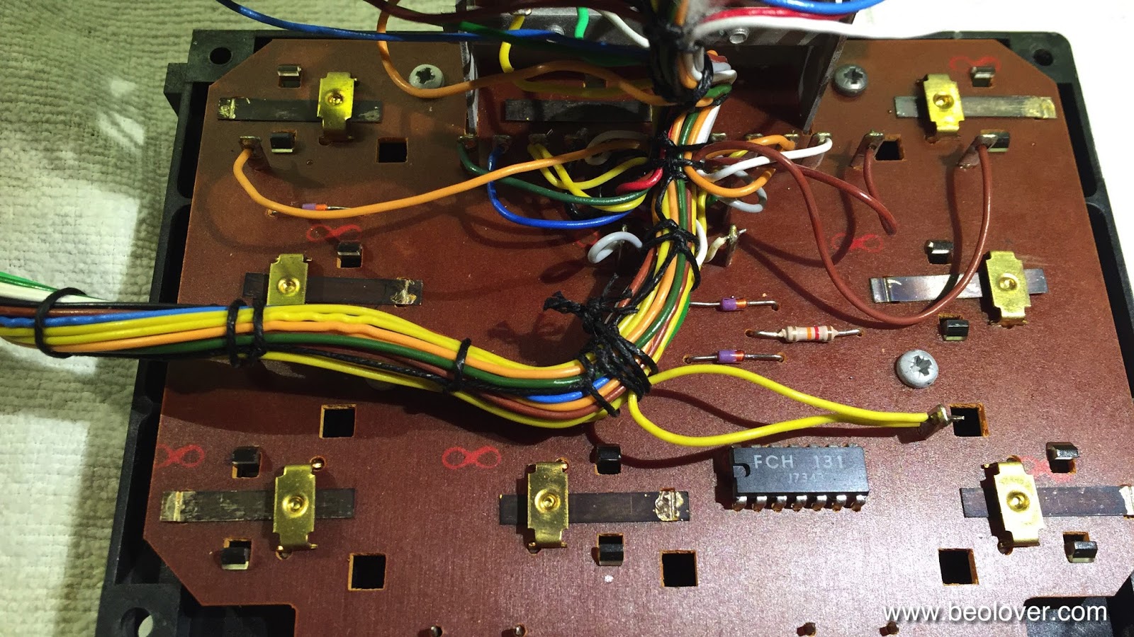
The upper board contains some of the logic chips and the light bulbs that illuminate the position indicator and the RPM trimmers. The lower PCB is populated with the eight switches for the keypad and one more logic IC. As usual, the switch terminals were heavily corroded:
I removed the board from the keypad, which is necessary for extracting the switch terminals:
This shows the side of the board that houses the switch actuators. The small green, white and grey 'plungers' are actuated by the keys on the keypad, which pushes the switch terminals on the other side of the board making or breaking the associated contact. Note the location of the single grey plunger top left. This is the wrong location for this particular one. It needs to be in the center of the bottom row, since this particular switch is a break switch. This incorrect installation immediately explained the malfunction of the arm lowering circuit that I noticed after the restoration of the main PCB. The green plungers are longer, and therefore this switch, which is responsible for lowering the arm, was permanently open (actuated). This shows the three switch types in comparison:
The grey one is the shortest. It is used for break switches. The green one is used for make switches and the white one is for two-pole make/break switches (the << and >> keys, which have slow and fast functionality, depending on how hard the keys are pressed).
I removed the switch terminals:
After removal of the oxide layer with 2000 grit sand paper, I coated the terminals with a gold layer:
and then soldered them back into place:
The final step was to replace the light bulbs with LEDs. The position indicator scale lights were replaced with custom designed LED boards (available to other B&O enthusiasts), each containing two red-green LEDs tuned to yield an incandescent-like sheen. The RPM trimmer back light bulbs were replaced with standard red LEDs and current limiting resistors:
This shows the LEDs in action after installation:
After that it was time to put the keypad back together. Unfortunately, the center key was not attached to the keypad, i.e. I needed to reinsert it. This can be difficult and there is a danger to scratch the other keys while doing it. For this reason I used 3D printed tools that I developed earlier, which make this process much easier. They allow pre-bending of the spring that holds the pad in place and that allows it to bounce back after pressing it:
Once the spring is bent up, it is fairly easy to get the pad on it. Careful removal of the printed taps releases the spring holding the key in place. And this shows the pad installed:
A test revealed that all keys are now working properly. On to gold coating the remaining switches below the carriage and in the arm lowering mechanism.


Sunday, November 26, 2017

Beogram 4000: Restoration of the Keypad

After restoring the arm carriage components of the Beogram 4000 that I am rebuilding right now, it was time to do the keypad. The keypad is the command center of the turntable and contains the TTL logic components of its 'early stage' digital control system. The keypad needs to be removed before one can get to its components. A single screw holds it in place:
The remarkable feature of this particular keypad was that there were no wires visible underneath it. All the other 4000 had the keypad wiring folded directly behind the latch that is bolted down. When I pulled this keypad up I found this arrangement:
An interesting way to do it, letting the wire harness enter the pad from the front. And much less painful to arrange when putting the pad back into its bay. This is how the harness exits the keypad in this arrangement:
Anyway, I thought I go on the record with this finding...You may think Beolover = Beonerd, I could not possibly comment...;-). On to the restoration:

This shows the keypad extracted:
and in 'service position':
The first item to take care is to replace the often frail light bulbs that illuminate the arm position scale and the RPM trimmers. This is the original arrangement:
I replaced the scale bulbs with my red/green LED based assemblies
Like all Beolover parts shown on the blog, they are available to other enthusiasts. Just send an email or use the contact form to the right if you are interested. The RPM trimmer illumination bulbs can be replaced by regular red LEDs and appropriate resistors to limit the current (they run at 12V...):
This shows the LEDs installed:
And 'in action':
The next step was to clean the switch terminals that were oxidized as usual. I pulled 2000 grit sand paper strips through the switches while actuating them. This cleaned the contact area from oxide. Subsequently, I coated them with a bit of DeoxIT D100 to slow down re-oxidation. One of the switches, which is under the 'down' key, needs special attention since it is hard to reach under the keypad hinge. It is best to extract it that the oxide can be cleaned off properly in the contact area. This is how it looked as extracted:
and after gently sanding it:
After I reinstalled the terminal, I checked all switches for proper contact resistance with a multimeter and then I put the pad back together. This is how the LEDs appear from the top of the pad:
Please, note that the position indicator was not installed when I took this picture. This concludes my work on the keypad. On to the electronics and the motor.


Tuesday, October 10, 2017

Beogram 4002 (5523): Restoration of the Worn Keypad

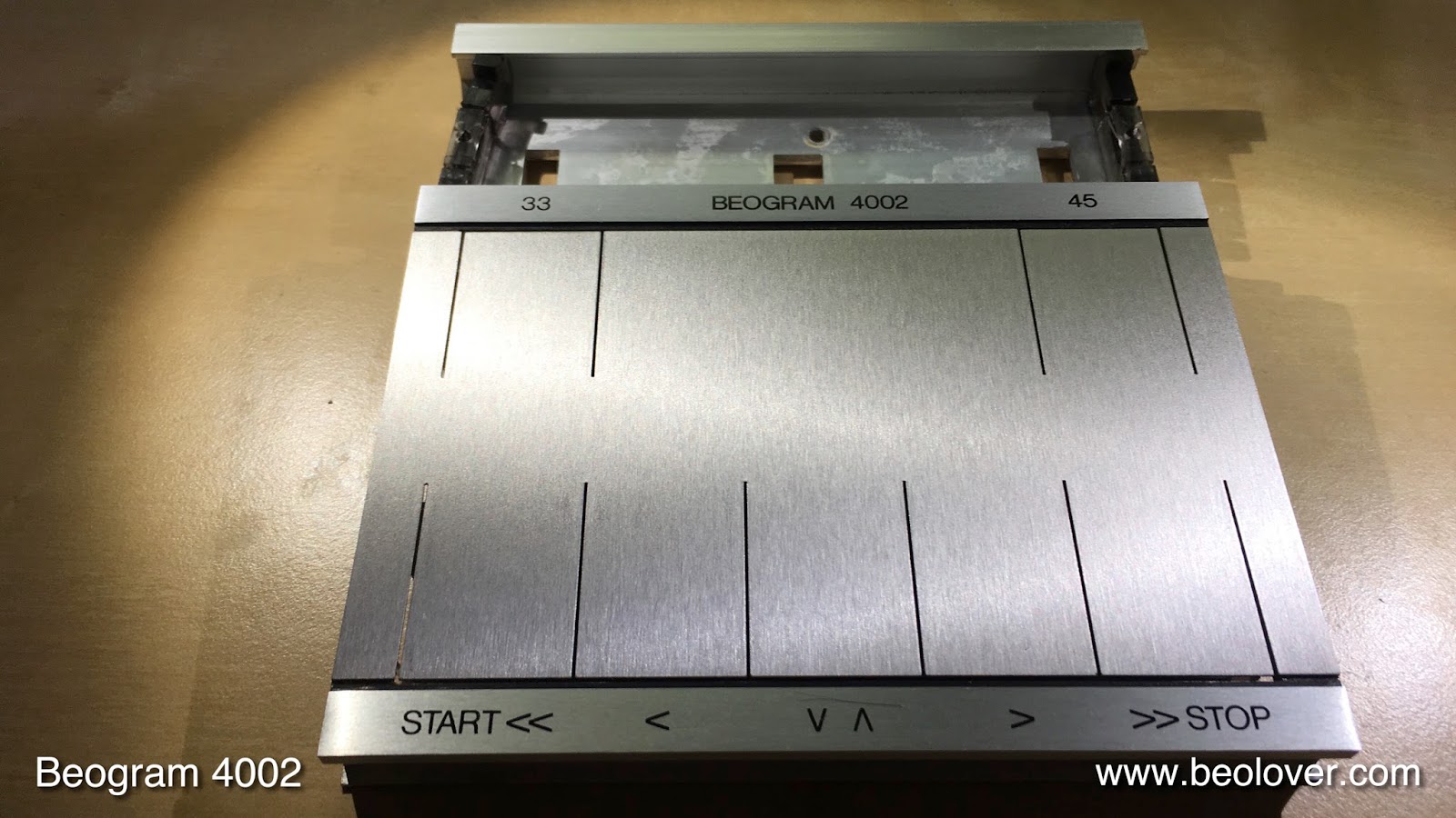
Like so many Beogram 4002, the 5523 Type that I am restoring right now also needed the keypad rejuvenated. It had the usual worn start key. This shows the keypad in the as-received condition:
After the restoration it looked like this:
We recommend to only use a soft cloth to operate these keypad, restored or original, to prevent interaction of the coating with the acids and grease present on fingers, and to reduce mechanical friction. Another option would be to install a Beolover 4002 Commander remote control, which allows to use the 4002 without any mechanical interaction with the keypad.

On to polishing the hood of this increasingly lovely Beogram 4002.


Tuesday, March 8, 2016

Beogram 4000: Replacing the Light Bulbs in the Control Panel and Gold Plating of the Keypad Contact Terminals

The next step in my current Beogram 4000 restoration process was to rebuild the control panel. I usually replace the incandescent light bulbs with LEDs and clean the key pad contacts. In this unit three of the four bulbs were broken, confirming that it is a good idea to switch to LEDs. LEDs have a much better reliability than incandescent bulbs.
This shows the original bulbs:
I recently had the SMD LED boards that I designed to replace the position scale illumination bulbs (the two on top) professionally manufactured. Here is an impression of the redesign:
This shows the boards installed. I also replaced the two bulbs that illuminate the red RPM trimmer shafts from below with red LEDs:
After replacing the bulbs I turned my attention to the contact terminals of the switches that are actuated by the keypad. They were highly oxidized:
Inspired by some pictures a customer sent me recently where he had his contacts Ni plated I decided to gold-plate these contacts. I extracted the terminals, cleaned them with a fiberglass pen, and then I electroplated them. Here is an impression of the as-original terminals after extraction:
and after gold plating:
After the plating process I reinstalled them:
Very pretty! This is Beolove!

I noticed that one of the two brackets that hold the strobe mirror in place was missing. So I printed myself a replacement:
and epoxied it in place:
Loosing this mirror would be a difficult item to fix, so it is better if that is prevented right from the start!

After this I had a look at the switches that are triggered by the carriage. They usually are also oxidized, but in this case I found a pristine situation. Maybe this board was replaced at some point. It looks almost new!:
I left them as they were and just gave them a light Deoxit D100 coating to reduce potential oxidation down the road.


Monday, November 2, 2015

Beogram 4000: New Arrival from Italy

Exciting! Another Beogram 4000 found its way to my bench for a full restoration! TNT brought it over to the US in an amazing three days. I extracted it from the box. It was quite well packed and arrived safely. The exterior of the unit is pretty decent. No damages to the veneer and the hood is absolutely polishable:

The aluminum trim in the back of the hood came off on one side, but that can be fixed with double sided tape. After I opened it up and removed the aluminum plates (which are in dire need of a deep cleaning) I found that the carriage pulley had come off during transport:

Luckily the parts were easily found in the enclosure:

As usual the main key of the control pad extracted itself from the spring that holds it in place. This proves that it is absolutely necessary to tape the keys down for transport. I reinstalled the pad, switched the unit to 110V and plugged it in (keenly watching for potential smoke...;-). Nothing happened, so I pressed 'ON' and the carriage set itself into motion in search for a record. It stopped as expected at the set-down point for 12" vinyls. So far so good. However the solenoid did not engage. I moved the assembly a few times up and down by hand and then tried again, and there was a life sign. Very reluctantly the tone arm lift engaged after a tired motion of the solenoid plunger...
The unit came with the indication that the arm would not lower. It is clear that this unit needs a full clean and rebuild of the solenoid/arm mechanism. Also the solenoid looks strange and may be a non-B&O part. Other than that I found that the RPM switches are oxidized and do not work every time one presses them. The restoration will cure all that. On the good news end a working strobe light can be noted. 

In my opinion one of the intriguing features of the 4000. The position indicator, which is another remarkable design feature, was already broken once and glued back together. This indicates that this unit was in 'expert' hands at some point. The glue job is fairly well, done, though. 
Furthermore, the indicator light bulbs are dead. My SMD LED replacements will fix that for good. All in all I am pretty confident about this project. This Beogram 4000 is a good starting point for a full restoration, which will take it to near-new performance and looks.


Friday, October 2, 2015

Beogram 4002 (5513): Replacing the Tracking Sensor Light Bulb with a Plug-In Ready SMD LED Assembly

Yesterday, I installed my latest version of the SMD LED light source for the tracking sensor of the Beogram 4002 (5513) that I am currently restoring.

A while ago I developed a drop-in ready SMD LED based assembly for replacing the incandescent bulb fixture. While this worked great, it still required the application of the inconvenient original tracking sensor sensitivity adjustment process. The mechanical positioning of the light sensors relative to the light source is quite tricky, and it is always chore to get this adjustment precisely right. The reason for this is that the mechanism is quite sensitive, while the adjustment mechanism is pretty coarse, requiring a lot of trial and error to get the adjustment right.

A recent beolove-affair with a Beogram 4000 taught me a better way to get this adjustment right: Add a trimmer potentiometer to the LED circuit, which allows the adjustment of the intensity of the LED. This gives an additional adjustment parameter that enables a straight forward fine tuning of the tracking response. I liked this a lot in the 4000, so I adapted the approach to the 4002's higher bulb voltage.

I made a short video about the installation and the tracking response adjustment process for this new design:


Here are a couple high-res pictures of the new LED assembly. I will be happy to provide this part to other enthusiasts!. This shows the added trimmer:

And this is a shot of the bottom side. The LED is in the same spot as the filament of the original light bulb assembly. The body of the replacement part is 3D printed and has the same shape as the lower part of the original fixture. This ensures a precise fit onto the light sensor assembly below the aperture:


This shows the part installed:


Monday, September 21, 2015

Beogram 4002: Replacing the RPM Indicator Bulbs with SMD LEDs

I continued working my way through replacing the lightbulbs in the Beogram 4002 (5513) that I am restoring right now. Today was RPM indicator day. I took this as an opportunity to further improve my LED replacement approach. In an earlier post I described how to replace the incandescent bulbs with the red and green LEDs of a RGB through hole 5 mm LED. This worked fairly well, but I was not 100% happy with the homogeneity of the back illumination of the RPM trimmer scales. The issue with standard through hole LEDs is their directed emission pattern out of the top of the LEDs. This made it necessary to sand their bulbs into a matte surface and also painting the tops black to prevent a too high emission on one side of the trimmer scales. 
My latest approach is based on my current approach to implanting LEDs for the position scale illumination of Beogram 4000s. I changed the PCB shape to fit behind the bulb covers of the 4002 bulb housings, and I adapted the current limiting resistors (10k for green and 2.5k for red) to the 21V operating voltage and the different illumination angle of the diffusing cavity. I made a short video about this updated approach:


Wednesday, September 9, 2015

Beogram 4000: Replacing the Tracking Sensor Incandescent Bulb with a Drop-In SMD LED Assembly and a Peek at the Opto-Resistors

The fourth light bulb that was broken in this Beogram 4000 was the tracking sensor bulb. I would have replaced it anyway. My recently developed SMD LED based replacement assembly works very well now in several Beogram 400x, and why risk a bulb failure down the road if this can be done with a LED, that most likely will survive the next 50 years? I use high efficiency white LEDs, which I run at a very low power level. This will make them last very long. Also it reduces the power consumption of these units, which is a concern due to the main transformers occasionally giving out, since they are not very over dimensioned, i.e. run close to their rated power. If all LEDs are replaced this way this can easily reduce the power intake by a few Watt, corresponding to a 10-20% current reduction in the transformer.
Anyway, here are a few impressions of this procedure. Details and instruction for the implementation of the drop-in ready assembly and the necessary adjustment of the tracking mechanism can be found in this video.
This shows the original light bulb assembly:

This shows the replacement design. The blue part matches the lower half of the original bulb housing shape to shield the opto-resistors in the sensor from ambient light. The PCB carries the LED and current limiting resistor, as well as a trimmer potentiometer to adjust the intensity of the LED. This is a great upgrade for fine tuning the tracking sensor performance to B&O spec (see video).

This shows the light source assembled from the bottom. The left 'window' contains the LED, which is located close to the original position of the bulb filament.


This shows the unit from the top. There is only one contact lead since the other contact is made to GND via the mounting screw. This simplifies the implementation of the assembly:


Here it is installed:
A test revealed that the LED performed as designed. 

Before I got it to work, however, this particular Beogram 4000 surprised me after the installation with a tracking mechanism that would only work in reverse direction (check the video for a demo - the 4000 can actually track a record in reverse direction, which makes it different from the later 4002 and 4004 models). I removed the bottom part of the tracking sensor unit, which contains the two sensors that control the carriage motor movement to check the two opto-resistors. My fear was that one of them had died. Here are a few pictures of how this assembly looks like.
This shows the top. You see the two slots under which each one sensor is placed. Depending on which one is brighter the carriage moves left or right. 

This shows the bottom:

Lovely old semiconductor devices. This is one of the reasons why I like this design so much. It is from a point in time where circuit design started taking quantum leaps due to the advent of integrated and other more advanced semiconductor devices.
Anyway, a test of the sensors showed that they worked. Here is what I measured: Several MOhms in darkness, and about 1 kOhm when blasting them with a quite bright white LED desk lamp. Both showed identical values indicating that I was searching at the wrong location for the root cause of the tracking issue. 
Of course, what I found was a cracked trace on PCB #6 that connects the sensor to the rest of the circuit. One of the pads that connect the 24V rail to the upper end of the sensors broke from the connecting trace. I fixed this by soldering a short extension to the sensor lead in question. You can see it in the above picture if you look closely.

Now the deck was ready for the tracking sensor adjustment procedure. I did pretty much exactly what I show in the video. First, I adjusted the sensor position mechanically using the excenter and then after being close to the prescribed two-record rotations, I used the trim pot to get a precise two rounds. I think I will implement this trim pot also in future Beogram 4002/4004 restorations. It just takes all the pain out of the adjustment process and makes it a quick affair.

Here you see it in action playing Somethin' Else by Cannonball Adderley on Blue Note: