Featured Post

Beolover SyncDrive: DC Platter Motor Replacement for Beogram 4002 and 4004 (Type 551x and 552x)

Late Beogram 4002 and the 4004 (Types 551x and 552x), which have DC platter motors instead of the earlier synchronous AC motors usually suff...

Showing posts with label bulbs. Show all posts

Tuesday, February 6, 2018

Beomaster 6000 (2702) restoration: FM main dial screen

The dial cord that activates the FM potentiometer through a big circular wheel and shaft also serves as the link to a band with a red dial to indicate the FM channel frequency. This dial band is attached to the cord with a small plastic clip that is glued to the back of the dial band. Unfortunately this clip was broken. Apparently some glue was put on in the hope to keep the cord in place. This may have worked for some time but finally got detached again.
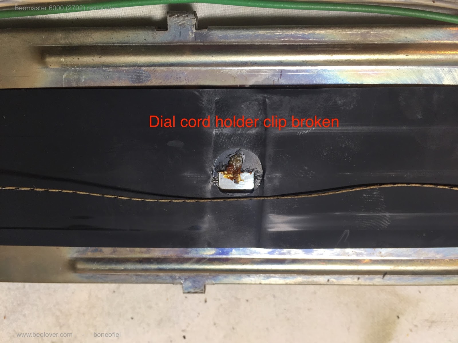

I wanted to re-fabricate the plastic clip and therefore it needed to be removed. Turned out not to be an easy task. The band is very fragile. Think of it like the magnetic reel-to-reel tape or cassette type of stuff. Anyhow I got it of with some light damage to the band.


Because of the damage, I made the new plastic clip a bit larger to cover completely the damaged area and have a strong bond between plastic and tape. Off course I first checked if this would not harm the free movement of the band over the complete width. The clip was made out of 1mm thick plastic sheet. Exactly the same thickness as the original one.


This clip was then glued wit Pattex GOLD to the tape and some pressure used for an hour.


I used this time to further overhaul the dial screen. The plastic rollers at both ends where removed, cleaned, greased and put back. Also the 4 glass bulbs where replaced with new ones.


The new clip is firmly in place now.


And now time to test the dial screen for good illumination !


Friday, January 15, 2016

Beogram 4000: Alternate "Circuit Diagram 2" with 24V Scale Illumination Lamps

I recently obtained a fairly pristine service manual for the Beogram 4000 and it came with a remarkable inserted leaf showing an alternate Circuit Diagram 2 (the 'executive' part of the control system). As far as I can tell the main difference on this diagram is that the position scale illumination is provided by two 24V bulbs connected in parallel to the 24V rail instead of the usual 2x 12V bulbs in series. I almost wish I hadn't found this diagram, since my simple question to Sonavor (who is currently restoring his 4000 -see his very awesome and detailed thread on beoworld.org) whether he wanted 24V or 12V versions of my bulb LED replacements tricked us both into believing he had the 24V version. More wishful thinking (at least on my part...;-) than reality, since it turned out he in fact has the 'normal' 12V version. Anyway, I decided to generate a high resolution scan of the circuit diagram in question for the enjoyment of all interested B&O aficionados. Here it is (click on the pic to get a glorious 8Mb 1200 dpi version):


Monday, November 2, 2015

Beogram 4000: New Arrival from Italy

Exciting! Another Beogram 4000 found its way to my bench for a full restoration! TNT brought it over to the US in an amazing three days. I extracted it from the box. It was quite well packed and arrived safely. The exterior of the unit is pretty decent. No damages to the veneer and the hood is absolutely polishable:

The aluminum trim in the back of the hood came off on one side, but that can be fixed with double sided tape. After I opened it up and removed the aluminum plates (which are in dire need of a deep cleaning) I found that the carriage pulley had come off during transport:

Luckily the parts were easily found in the enclosure:

As usual the main key of the control pad extracted itself from the spring that holds it in place. This proves that it is absolutely necessary to tape the keys down for transport. I reinstalled the pad, switched the unit to 110V and plugged it in (keenly watching for potential smoke...;-). Nothing happened, so I pressed 'ON' and the carriage set itself into motion in search for a record. It stopped as expected at the set-down point for 12" vinyls. So far so good. However the solenoid did not engage. I moved the assembly a few times up and down by hand and then tried again, and there was a life sign. Very reluctantly the tone arm lift engaged after a tired motion of the solenoid plunger...
The unit came with the indication that the arm would not lower. It is clear that this unit needs a full clean and rebuild of the solenoid/arm mechanism. Also the solenoid looks strange and may be a non-B&O part. Other than that I found that the RPM switches are oxidized and do not work every time one presses them. The restoration will cure all that. On the good news end a working strobe light can be noted. 

In my opinion one of the intriguing features of the 4000. The position indicator, which is another remarkable design feature, was already broken once and glued back together. This indicates that this unit was in 'expert' hands at some point. The glue job is fairly well, done, though. 
Furthermore, the indicator light bulbs are dead. My SMD LED replacements will fix that for good. All in all I am pretty confident about this project. This Beogram 4000 is a good starting point for a full restoration, which will take it to near-new performance and looks.