Featured Post

Beolover SyncDrive: DC Platter Motor Replacement for Beogram 4002 and 4004 (Type 551x and 552x)

Late Beogram 4002 and the 4004 (Types 551x and 552x), which have DC platter motors instead of the earlier synchronous AC motors usually suff...

Showing posts with label plastic. Show all posts

Sunday, April 26, 2026

Beogram 4002 (5503): New Monolithic Beolover Carriage Position Sensor for AC-Motor Beogram 4002 (Types 550x)

A little more than a year ago I designed a replacement part for the carriage position sensor PCB in DC platter motor Beogram 4002 and 4004 (Types 551x and 552x). This board takes the guesswork out when the carriage position sensor does not work properly. The original design is fairly sensitive to the alignment between the IR diode and the photoresistor, as well as the alignment of the ruler relative ot the sensor, and it can be tedious to get everything properly adjusted.

The Beolover Carriage Position PCB for Beogram 4002 and 4004 (Types 551x/552x) is based on a modern monolithic IR photo-interrupter and circuitry that generates a clean and precise digital output signal for driving 1TR17 on the main PCB.

Sadly, this solution only works in the later DC motor Beograms. The earlier Beogram 4002 with AC platter motor has a much more complicated hard-wired carriage position sensor PCB that is not very easily replaced. But when I recently restored an AC motor Type 5503 Beogram 4002, and it gave me grief with detecting the runout groove reliably, I thought it would be nice to have a solution for these models, too!

Since replacing the entire board is complicated and unnecessary, I designed a replacement for just the sensor part of the board. I designed a board that simply piggybacks onto the main PCB, replacing only the original sensor bulb and photoresistor. This board adapts the same reliable circuit that I used on the DC motor PCB. 

This shows the final version of the Beolover Carriage Position Sensor for Beogram 4002 (Types 550x):


Let's see how it is installed:

This shows the original setup. The photoresistor is in the black housing in front of the 'plexiglass ruler' bolted to the carriage assembly:


After removing the two screws that hold the ruler assembly in place, it can be removed. This reveals the black bulb housing under the ruler.
Here is a view from a different angle (I already had the orange capacitor and white solenoid resistor replaced when I took this photo):
After removal of the bulb cover, the bulb is visible:
The first step for the installation of the new Beolover Carriage Position Sensor for Beogram 4002 (Types 550x) is removing both the photoresistor and the bulb and cleaning the five solder pads indicated below of all solder:
This is best done with a desolder gun since the pads need to be clean and flat so that the Beolover board can be placed onto the original board surface. The board needs to be aligned as shown in the picture below:
This shows it aligned and soldered in place:
When aligned properly, the three round connection vias on the Beolover board are aligned with the respective solder pads where the board connects to power and the base of 1TR17. All that needs to be done at this point is to put a bit of solder inside the vias.
It is a good idea to solder one via first and then adjust the board precisely, while making sure it is fully flat on the original board surface. If it is not flat or misaligned, it may be difficult or impossible to adjust the plastic ruler for proper function of the position sensor.
This shows the plexiglass ruler assembly bolted back into place. 
Adjust the ruler that runs at a constant ~1mm distance from the front-facing part of the sensor during the entire travel of the carriage.
Flipping the switch in front of the sensor activates the on-board LED:
The LED makes it easy to test the proper functioning of the sensor. It should light up whenever a black bar passes between the legs of the sensor.

After installation of the sensor, the Beogram reliably recognized the runout grooves of all records I played. Beautifully!


Tuesday, February 6, 2018

Beomaster 6000 (2702) restoration: FM main dial screen

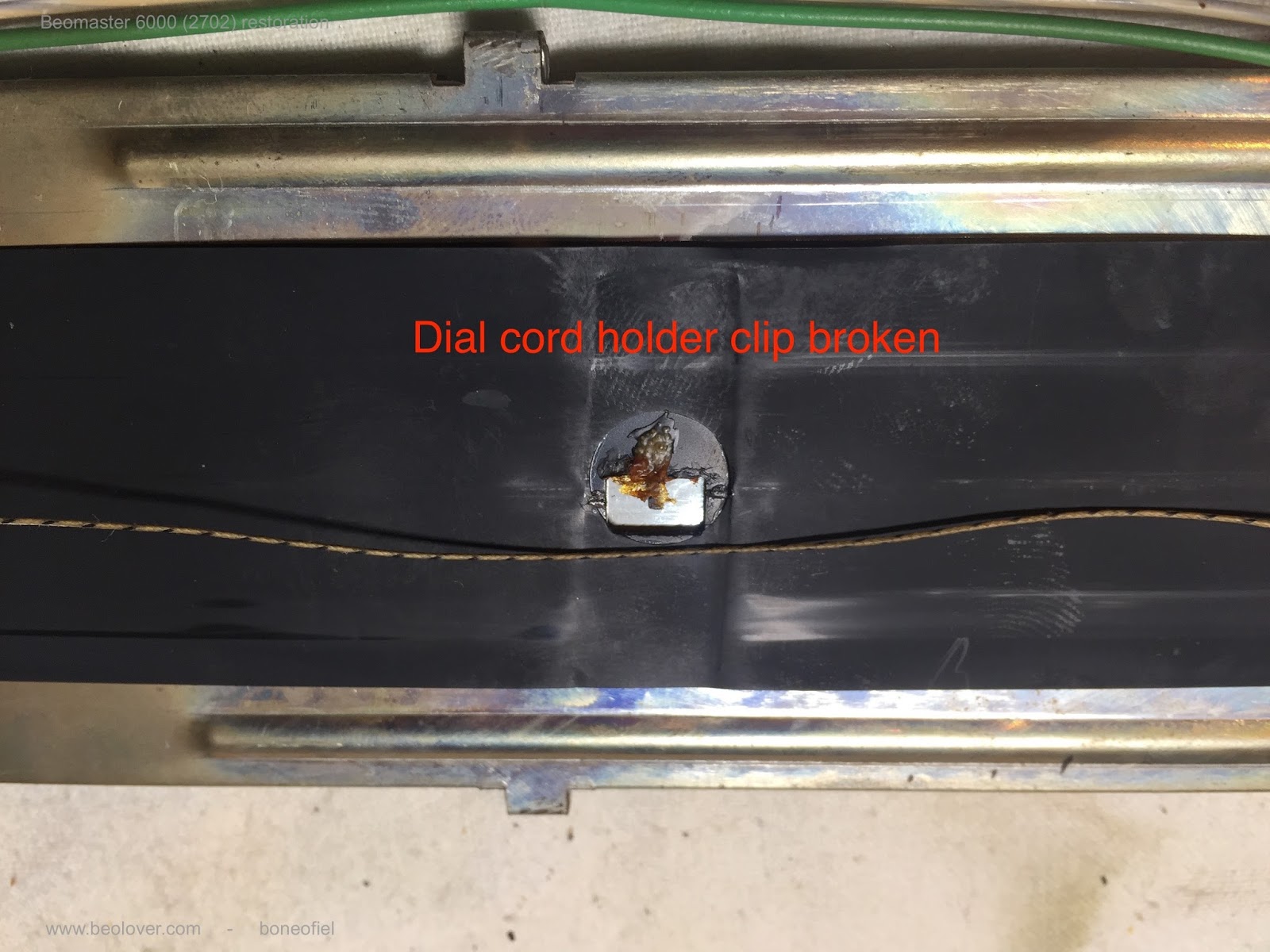
The dial cord that activates the FM potentiometer through a big circular wheel and shaft also serves as the link to a band with a red dial to indicate the FM channel frequency. This dial band is attached to the cord with a small plastic clip that is glued to the back of the dial band. Unfortunately this clip was broken. Apparently some glue was put on in the hope to keep the cord in place. This may have worked for some time but finally got detached again.


I wanted to re-fabricate the plastic clip and therefore it needed to be removed. Turned out not to be an easy task. The band is very fragile. Think of it like the magnetic reel-to-reel tape or cassette type of stuff. Anyhow I got it of with some light damage to the band.


Because of the damage, I made the new plastic clip a bit larger to cover completely the damaged area and have a strong bond between plastic and tape. Off course I first checked if this would not harm the free movement of the band over the complete width. The clip was made out of 1mm thick plastic sheet. Exactly the same thickness as the original one.


This clip was then glued wit Pattex GOLD to the tape and some pressure used for an hour.


I used this time to further overhaul the dial screen. The plastic rollers at both ends where removed, cleaned, greased and put back. Also the 4 glass bulbs where replaced with new ones.


The new clip is firmly in place now.


And now time to test the dial screen for good illumination !


Friday, January 1, 2016

Beogram 4002 (5513): Adjusting the Sub-Chassis and the Platter, and RPM Calibration

Today I it was time to give the Beogram 4002 (5513) that I am currently reviving a properly adjusted platter and sub chassis. The goal is to adjust everything that the aluminum surface of the platter is flush with the aluminum panels surrounding it, while having the sub chassis centered between the upper and lower limits of the transport locks and the arms being also parallel to the aluminum surfaces. This is usually a pretty delicate process since so many things need to align. I have now a bit of experience with this and so after a while this Beogram looked very nice and up to spec. I recently made a couple videos that demonstrate this process:


Once the platter was adjusted I did a baseline RPM adjustment for 33.33 and 45 RPM using my recently developed BeoloverRPM device. Here is a picture of it in action:


This shows the readout after I already had adjusted 33.33 and then did 45:

Stabilizing
Measurement starts
time: 0:0:9 RPM: 33.381
time: 0:0:20 RPM: 33.3782
time: 0:0:31 RPM: 33.3904
time: 0:0:42 RPM: 33.3987
time: 0:0:53 RPM: 33.4052
time: 0:1:4 RPM: 33.3937
time: 0:1:15 RPM: 33.4039
time: 0:1:26 RPM: 33.3882
time: 0:1:37 RPM: 33.3958
time: 0:1:48 RPM: 33.3817
time: 0:1:59 RPM: 33.3982
time: 0:2:10 RPM: 33.4025
time: 0:2:21 RPM: 33.4117
time: 0:2:32 RPM: 33.4088
time: 0:2:43 RPM: 33.3933
time: 0:2:54 RPM: 33.3916
time: 0:3:5 RPM: 33.3879
time: 0:3:16 RPM: 33.3815
time: 0:3:27 RPM: 33.4003
time: 0:3:38 RPM: 33.4095
time: 0:3:49 RPM: 33.4057
time: 0:3:54 RPM: 35.24
time: 0:3:55 RPM: 38.32
time: 0:3:56 RPM: 40.9
time: 0:4:0 RPM: 44.4733
time: 0:4:11 RPM: 44.8362
time: 0:4:22 RPM: 44.8325
time: 0:4:33 RPM: 44.8564
time: 0:4:44 RPM: 44.8543
time: 0:4:55 RPM: 45.0447
time: 0:5:6 RPM: 45.1634
time: 0:5:17 RPM: 45.1921
time: 0:5:28 RPM: 45.1968
time: 0:5:39 RPM: 44.8451
time: 0:5:50 RPM: 44.8174
time: 0:6:1 RPM: 45.2279
time: 0:6:12 RPM: 45.2203
time: 0:6:23 RPM: 44.7694
time: 0:6:34 RPM: 45.1452
time: 0:6:45 RPM: 45.2124
time: 0:6:56 RPM: 45.1949
time: 0:7:7 RPM: 45.1759
time: 0:7:18 RPM: 45.1953
time: 0:7:29 RPM: 45.2055
time: 0:7:40 RPM: 45.1998

It turns out that it is pretty difficult to adjust the RPM precisely with the standard single turn RPM trimmers that are in the Beogram originally. You can see at the and how I tried to get close to 45, but I always missed it by 0.2 or more by just very slightly moving the trimmer. This demonstrates that it is a great idea to put in multi-turn trimmers to get this right. On the other hand, I think it is difficult to hear such small difference...so this deck sounds now pretty good, especially with the lovely MMC20CL cartridge that came with it. I am listening to 'Song for My Father' by Horace Silver on Blue Note on it right now while writing this post! Wonderful!


I will give this Beogram some more listening to make sure there are no intermittent issues, but I think it is ready for duty again. This is Beolove!


Thursday, December 31, 2015

Beogram 4002 (5513): Repair of a Broken SO ('Shut Off') Switch

This is a follow up to my last post about a SO ("Shut Off") switch that had lost its plastic actuator and hence caused trouble during shutdown of the deck. I set out to develop a 3D printed part to replace the missing plastic part. This shows the SO (left) and the ES ("End Switch", right) in comparison. The ES still has its plastic appendage, while the SO is missing it.

I took measurements and then went through a few 3D printing iterations to get a part that would come out right. Due to the small size this was pushing the limits of the 3D printer, so the outcome was significantly difficult from the 3D CAD design, and experimentation finally yielded a useful shape:

I glued it on with epoxy:
And now this Beogram can shut down again in an orderly manner:

On to the sub-chassis and platter adjustment.


Wednesday, December 17, 2014

Beogram 4002/4004: 3D Printed Cabinet Guiding Washers

I am getting closer to finishing up my Beogram 4002. One of the still remaining annoying issues was the loose cabinet, which would not remain in its locked position due to the absence of the guiding washers that hold it in place. In the 4002 these washers were made from plexiglass, which easily cracks during the rigors of transport or just due to old age.
I opened up my Beogram 4004 to see how things look inside there, and it turns out that the 4004 has metal parts instead of the plexiglass ones in the 4002. I took measurements of one of those washers, and printed replacements on a Formlabs Form 1 stereolithography printer.

Here is a picture of the results: 


I also made a short video to demonstrate the functionality of the guiding washers:


The video shows that the new washers perform well. They are a bit elastic since the stereolithography printer plastic appears to be that way, so one needs to be a bit careful to not over tighten the screws when installing them. Otherwise, I was quite happy with the result. The cabinet slides snugly in its tracks.

Saturday, July 26, 2014

Beomaster 8000: 3D Printed Control Panel Linkage

This is the continuation of an earlier blog entry at http://beolover.blogspot.com/2014/06/beomaster-8000-3d-printed-controls-lid.html

I started reassembling the recently recapped Beomaster 8000. It was time to try out the 3D printed control panel cover linkage that I had printed a few weeks ago after finding that the original linkage had cracked and lost one of its hooks. 

I put in the 3D printed part (Makerbot II, PLA, highest density), and it worked nicely - for a few openings and closings - then it popped out at the damper. This meant that my part had a slightly too wide gap on that end, which would allow the damper arm to come loose. I redesigned the part in Inventor with a 0.2 mm smaller gap, and had it printed again. This time it worked very well. The part clicked in solidly, almost too tight. I lubricated it with Ballistol, which resulted in very smooth operation. 

I made a short YouTube video that gives some more info and shows the part installed and in action:


The STL file for the linkage is posted on my website at beolover.com:(http://beolover.weebly.com/control-panel-cover-linkage.html).


Thursday, June 12, 2014

Beomaster 8000: 3D Printed Controls Lid Linkage

I just received a 3D printed part for the Beomaster 8000 I am currently restoring. When it arrived I pressed "Programming" to access the controls, and the brushed aluminum cover popped open at an alarming speed, indicating that the damper was disconnected. Once opened the Beomaster up, this was confirmed. Sadly the plexiglass link lost its bottom end and therefore lost contact to the damper that prevents the cover from snapping open. Here is a picture of this sad state of affairs:


So I recently drew up this part in Autodesk Inventor, guesstimating the missing bottom end (I didn't have another 8000 open at that point to take measurements of a complete part). Then I had it 3D printed on a Makerbot II using black PLA: Here is the result:


I designed the holes a bit smaller, and then drilled them out with a 9/64 (right, lid) and a 11/64 (left, damper end) bit. The Makerbot has a hard time to get hole dimensions perfect on this size scale, and it is better to drill the material carefully to get a more machined feel for rotating joints like in this case.

I tested the part on the damper and the lid joints, and it seems to click into place fairly well...when I assemble the Beomaster again, we will see if this really worked (I am a bit concerned that it might disconnect from a joint when using the cover in a routine fashion - I will post an update on that).

Anyway,my fun with 3D printing continues!