Featured Post

Beolover SyncDrive: DC Platter Motor Replacement for Beogram 4002 and 4004 (Type 551x and 552x)

Late Beogram 4002 and the 4004 (Types 551x and 552x), which have DC platter motors instead of the earlier synchronous AC motors usually suff...

Showing posts with label housing. Show all posts

Sunday, April 26, 2026

Beogram 4002 (5503): New Monolithic Beolover Carriage Position Sensor for AC-Motor Beogram 4002 (Types 550x)

A little more than a year ago I designed a replacement part for the carriage position sensor PCB in DC platter motor Beogram 4002 and 4004 (Types 551x and 552x). This board takes the guesswork out when the carriage position sensor does not work properly. The original design is fairly sensitive to the alignment between the IR diode and the photoresistor, as well as the alignment of the ruler relative ot the sensor, and it can be tedious to get everything properly adjusted.

The Beolover Carriage Position PCB for Beogram 4002 and 4004 (Types 551x/552x) is based on a modern monolithic IR photo-interrupter and circuitry that generates a clean and precise digital output signal for driving 1TR17 on the main PCB.

Sadly, this solution only works in the later DC motor Beograms. The earlier Beogram 4002 with AC platter motor has a much more complicated hard-wired carriage position sensor PCB that is not very easily replaced. But when I recently restored an AC motor Type 5503 Beogram 4002, and it gave me grief with detecting the runout groove reliably, I thought it would be nice to have a solution for these models, too!

Since replacing the entire board is complicated and unnecessary, I designed a replacement for just the sensor part of the board. I designed a board that simply piggybacks onto the main PCB, replacing only the original sensor bulb and photoresistor. This board adapts the same reliable circuit that I used on the DC motor PCB. 

This shows the final version of the Beolover Carriage Position Sensor for Beogram 4002 (Types 550x):


Let's see how it is installed:

This shows the original setup. The photoresistor is in the black housing in front of the 'plexiglass ruler' bolted to the carriage assembly:


After removing the two screws that hold the ruler assembly in place, it can be removed. This reveals the black bulb housing under the ruler.
Here is a view from a different angle (I already had the orange capacitor and white solenoid resistor replaced when I took this photo):
After removal of the bulb cover, the bulb is visible:
The first step for the installation of the new Beolover Carriage Position Sensor for Beogram 4002 (Types 550x) is removing both the photoresistor and the bulb and cleaning the five solder pads indicated below of all solder:
This is best done with a desolder gun since the pads need to be clean and flat so that the Beolover board can be placed onto the original board surface. The board needs to be aligned as shown in the picture below:
This shows it aligned and soldered in place:
When aligned properly, the three round connection vias on the Beolover board are aligned with the respective solder pads where the board connects to power and the base of 1TR17. All that needs to be done at this point is to put a bit of solder inside the vias.
It is a good idea to solder one via first and then adjust the board precisely, while making sure it is fully flat on the original board surface. If it is not flat or misaligned, it may be difficult or impossible to adjust the plastic ruler for proper function of the position sensor.
This shows the plexiglass ruler assembly bolted back into place. 
Adjust the ruler that runs at a constant ~1mm distance from the front-facing part of the sensor during the entire travel of the carriage.
Flipping the switch in front of the sensor activates the on-board LED:
The LED makes it easy to test the proper functioning of the sensor. It should light up whenever a black bar passes between the legs of the sensor.

After installation of the sensor, the Beogram reliably recognized the runout grooves of all records I played. Beautifully!


Thursday, December 1, 2022

Beogram 4002 (5503): Restoration of the Carriage Position Sensor - Development of a New Beolover Part

The Beogram 4002 (5503) that I am currently restoring had a damaged carriage position sensor photo resistor housing, which had broken off mounting tabs:

I removed the photo resistor housing:
This shows it from the back:
After pulling out the bottom part, the photo resistor can be extracted:
I designed a replacement housing that I can print on a 3D printer. It consists of two parts. This shows them together with the extracted photo resistor:
This shows how to integrate the photo sensor with the assembly:
First straighten the leads of the photo sensor and put it on the insert part like this:
Then slide the main housing over the insert with the photo resistor:
This shows the assembled sensor from the bottom:
Now the assembly can be inserted into the original mounting cutouts:
Once the sensor has been clicked into the PCB, the leads can be soldered to the pads:
I decided to also replace the position sensor light bulb with an LED. This shows the original lightbulb lit up in its housing:
Removal of the housing reveals the light bulb soldered to its two pads:
The right pad is the 24V rail, while the left pad connects to GND via 1R91. It is easy to replace the bulb with a LED: Basically any LED will do. I selected an amber LED with a 2.1cd light output at 20mA that I had in my stash. Since it runs from 24V in this setup, a resistor needs to be put in series to limit the current. I selected a 3.3kOhm resistor that limits the current to about 7mA. This current lights the LED up in a low key way, similar to the output of the light bulb:
This shows the entire restored carriage PCB (I also replaced the 47u electrolytic capacitor and the 8.2 Ohm solenoid resistor):
After I installed the carriage again I tested the sensor output by measuring the collector voltage at TR23, which should give clean 24V signals every time a black segment of the 'plexiglass ruler' gets pulled between the LED and the photo resistor. This shows the signal that the 45 RPM pattern caused, while the carriage swept the platter:
This looks like it should, i.e. we can conclude that the restoration of the carriage position sensor was successful.


Thursday, April 23, 2020

Beomaster 4400 Type 2419: Power on/off switch rebuild completed

I had some time tonight to finish preparing the rebuilt Beomaster 4400 power on/off switch for re-installation into the receiver.

My method of wiring the switch this time was to cut and fit the bus bars first. Then I attached the relative wire pieces to the bus bars before attaching everything to the switch contacts.

When I did attach the mini-assemblies to the switch contacts I used some solder shield clamps to prevent any heat from reaching the plastic switch housing.

Here is the power on/off switch fully wired back up and ready for re-installation.


I was very pleased with the wire connection results.  Now to check the switch operation again.


Very nice. I exercised the switch actuator a bunch of times and never had a case of a contact failure.
The contacts in fact remained nice and solid. No movement in them whatsoever.

This switch is ready to be re-installed.

Wednesday, April 22, 2020

Beomaster 4400 Type 2419: Rebuild 2 of the power on/off switch

Using the various Beomaster 4400 power on/off switch piece parts I selected the best switch components to rebuild a good switch for this project.

I secured the new switch contacts in the top housing using some instant epoxy. It is pin point so I could just place a drop around each contact coming through the housing. That secured the contacts and allowed me to test fit the two switch housing halves to make sure the contacts go into their respective slots.

Here is a picture of the contacts and actuator in the top housing half ready for mating with the lower housing.  I have the contacts that open and close turned around so that I am using the unused sides of the contacts. These refurbished contacts look way better than what switch contacts looked like previously.


So far, so good.

I installed the actuator lever and the lower housing, then checked the switch operation with an ohmmeter multiple times.  The switch operated perfectly each time.


Satisfied with the rebuilt switch I sealed the two housings with a bead of black hot glue.  This type of glue does a great job of hold things together but can easily be peeled off it access to the switch contacts is ever needed again.


The next step will be to carefully connect the switch wiring (including the two wires to my arc suppression device) without overheating the plastic switch housing.

I am also designing how I will re-attach the switch to the Beomaster 4400 switching assembly. I will need to somehow strap it in place.

Tuesday, April 21, 2020

Beomaster 4400 Type 2419: Rebuilding another power on/off switch

I looked over the three broken Beomaster 4400 power on/off switch components. That included two sets of pretty badly charred contacts. When I first looked at them I figured I would just toss them away. Fortunately I waiting and thought about it more. I also did a little research and confirmed that I can't just go find and purchase replacement contacts. The best thing would to be to try and salvage what I have. Then I remembered one of the most important tools in the workshop...the Dremel.

I used the Dremel and an ultrasonic cleaner to refurbish the damaged switch contacts. The results came out pretty good I think. I finished up the cleanup with a Deoxit treatment on the contacts and here is what they look like now.


Here are the cleaned up switch housings and actuators.


I have a decent selection of parts now to come up with a working Beomaster 4400 power on/off switch.

This set of components looks like my best bet.


The large switch housing piece has the hole in it from a burned contact but the rest of it looks pretty decent. After I re-install the contacts I can fill that hole with some epoxy.

For mating the two switch housing halves I can use a bead of hot glue again but I am thinking about drilling and tapping three M2 screw holes where the wide part of the housings (where the old mating tabs are). If I go that route I will use nylon M2 screws to join the parts.

Once I have the stationary switch contacts pressed back into the smaller housing I will solder on some connection wires to use when I place the switch back into the Beomaster.  I will make sure I protect the plastic switch housing when doing that soldering this time around.

Saturday, December 5, 2015

Beogram 4002 (5521): Replacing the Tracking Sensor Light Bulb with a SMD LED

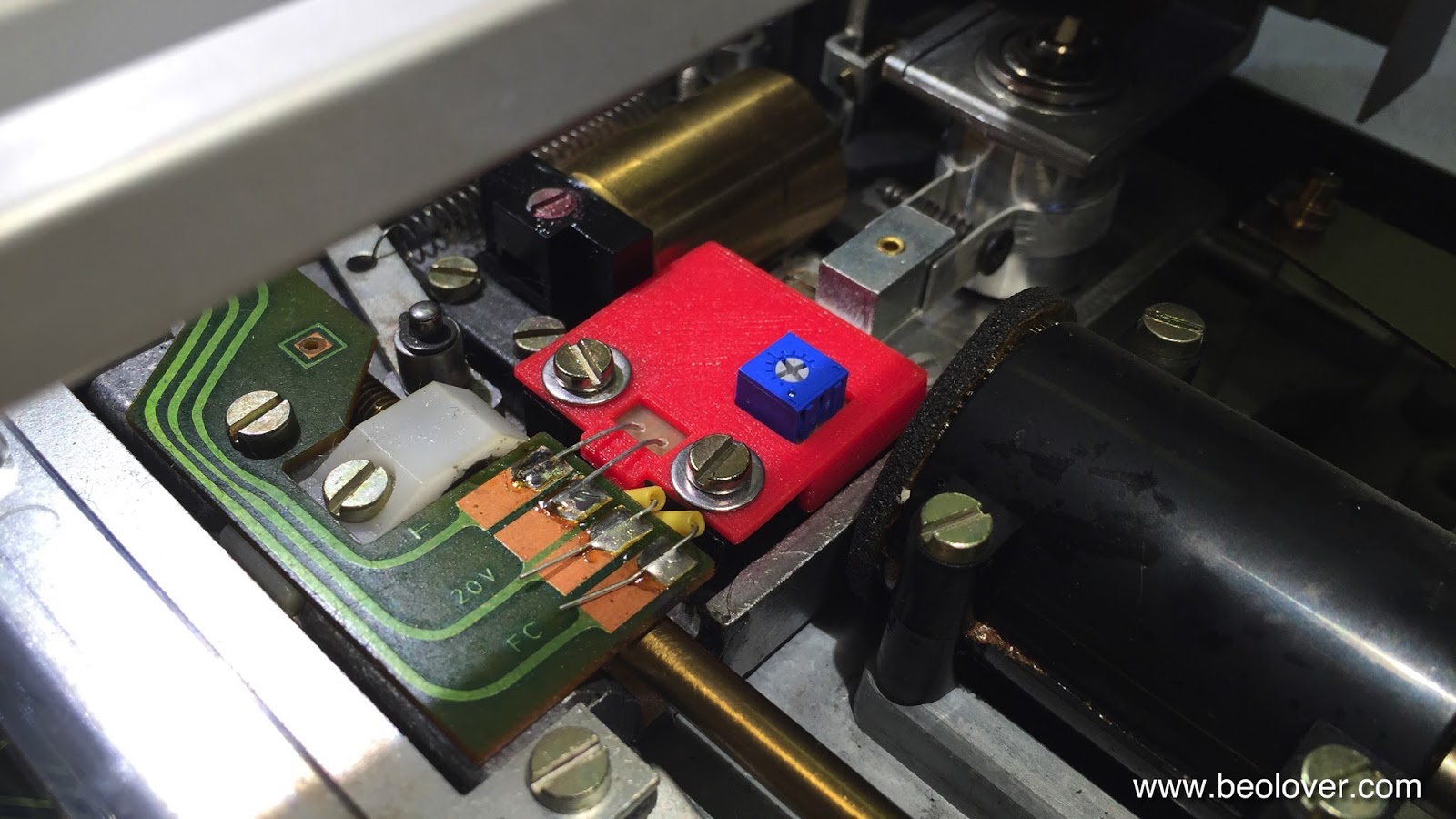
The Beogram 4002 that is on my bench right now came with a broken tracking sensor light bulb. I replaced the bulb housing assembly with my SMD LED based drop-in ready replacement part. This unit was recently redesigned on the occasion of a Beogram 4000 restoration to feature an integrated intensity trimmer, which makes the adjustment of the tracking sensor feedback much more straight forward. The trimmer allows to fine-tune the feedback after the mechanical positioning of the light sensors below the light source. The adjustment process is discussed in detail in this video

This shows the original setup of the tracking sensor:


Here is a picture of the latest iteration of my design in comparison with the original bulb assembly after I removed it from the tracking sensor:

This part is available to other B&O enthusiasts. Just send me an email.

This shows the installed part:

Once the LED assembly was soldered in, I performed the adjustment procedure as shown in my video to achieve that the carriage motor starts advancing after 2±1 rotations of the record after lowering the needle onto the record. This restored the basic functionality of this Beogram. On to replacing the RPM light bulbs with LED assemblies.