The first item to address in the Beogram 4000 that I recently received for a restoration was the broken cartridge mount. Here is a picture of the mount:
As in so many 4000s the plastic tab broke off. In this case the Beogram came with a 4002 arm installed that also has a damaged mount, and the original 4000 arm came along separated. Per customer instructions the 4002 arm was to be removed and be replaced with the original arm with a working MMC mount.
I decided to make this the first Beogram that I would outfit with my recently developed 3D printed replacement MMC mount. Sonavor's (Beoworld) reports about implanting one of them successfully into his own Beogram 4000 and using it for some time now without issues made me confident that this design may indeed be ready for primetime. So, in a way this post is a conclusion to my previous posts about the development process of the MMC mount replacement that can be found here and here.
I started out by assembling a replacement mount. This shows the 3D printed MMC mount body with the attached flex PCB that supplies the electrical contact terminals for the cartridge coils:
The next step was to get the damaged mount out of the original 4000 tonearm. They are glued into the aluminum tube, but this rule can be loosened in a boiling water bath:
After heating it for a few minutes (typically until the end of the aluminum tube becomes too hot to touch it comfortably) I put it into ice water for a few minutes. The I pushed the mount out with a metal rod. If you do this at home, be careful to not damage the wires in the tube. I bundle them neatly to one side and then carefully insert the rod (which is protected at the end with a bit of shrink tube to lessen the impact on potentially clamped in-between wires) and then slowly push the mount out:
This shows the two plastic parts separated with the original flex PCB separated:
this shows the original PCB in detail. Two of the contact points were already broken out:
I unsoldered the wires and put them onto the new mount in the same order. Then it was time to insert the new mount into the arm. Per Sonavor's recommendation I used Alene's Tacky Glue. This glue has the advantage that it can be overcome in case the mount needs to be replaced a second time in the future.
I found it a good idea to use a (broken..;-) cartridge to push the mount into the arm, since it needs to be a bit recessed to allow for the metal body of the cartridge to enter the arm by about 0.5 mm. This makes sure that the mount is just far enough back to ensure that there is no gap between arm and cartridge.
Now it was time to take the 4002 arm out to get things prepared for installing the repaired original 4000 arm. The first step is to remove the sole screw that holds the arm in place:
After removing the screw one can carefully pull the arm forward a bit to reveal the mounting tab that is underneath:
This tab is connected to an excenter (for adjusting the arm position on its mounting fixture) that has a spring on its actuator to hold the tab up:
Then I was able to pull the arm out to reveal the connecting PCB that is inside the arm. First, however I encountered a leaf spring that stiffens this setup a bit:
After taking it out the PCB was revealed:
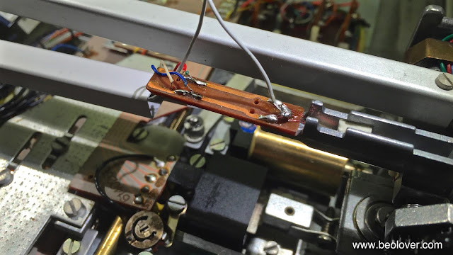
Now it was time to remove the jumper wires that connect to the cartridge. I first unsoldered the grey grounding wire (one needs to be careful to not accidentally also remove the very fine 'magnet wire' that makes the connection through the lateral arm pivot):
The signal wires that connect to the coils are attached to both the top and the bottom of the PCB. That makes it slightly more interesting to remove them:
Using a mirror is helpful to remove the bottom ones (white and red). And then the arm was liberated:
The installation of the original 4000 arm followed the above steps in reverse. A bit of practice may be needed to re-solder the bottom connections. However, it can be done fairly straight forward with a mirror.
Before I can try the new mount out I will need to get the rest of the deck going. On to rebuilding the arm lowering and tracking systems!


Hi, can I buy a 3d printed mount? I have the same fault with my 4000
ReplyDelete