Featured Post

Beolover SyncDrive: DC Platter Motor Replacement for Beogram 4002 and 4004 (Type 551x and 552x)

Late Beogram 4002 and the 4004 (Types 551x and 552x), which have DC platter motors instead of the earlier synchronous AC motors usually suff...

Showing posts with label cartridge. Show all posts

Saturday, August 1, 2026

Characterization of a MMC 6000 Cartridge Restored by Tonabnehmerservice.de in Comparison to Two Good Sounding Original Cartridges

I recently sold a fully restored Beogram 4002 (Type 5503 with AC platter motor) to a customer in California. The customer also wanted a newly rebuilt cartridge. He settled on getting a restored MMC 6000 from tonabnehmerservice.de. Franz Josef at tonabnehmerservice has provided a number of cartridges to some of my customers over the years, and they all seem pretty happy with his work. This particular cartridge is one of his top-of-the-line restorations with a beryllium cantilever and a nude Shibata diamond. 

In this case, my customer asked Franz Josef to send me the cartridge directly so I could check it out before sending it along with the restored Beogram. I received the cartridge last week. It arrived in a little box fitted with a proper plexiglass protector:

I carefully extracted it:

Looks very nice! This shows the beauty playing on the restored Beogram:


The test setup for cartridge characterization is simple. All I had to do was plug the Beogram DIN5 output plug into proper adapters to interface it with the BNC inputs of my new QuantAsylum QA403 audio analyzer. All measurements were done at 1.2g tracking weight (calibrated with a digital gauge).

A few years back I wrote a couple blog posts about this type of measurement. This one discusses the frequency response measurement and this one the 'trackability' measurement.

Let's focus on the frequency response first:

There are several ways to do it. In the old days, they used test tracks that actually played a frequency ramp from 20 to 20000 Hz. The cartridge was hooked up to an AC voltmeter, and a voltage vs. time plotter recorded the signal as the test track played. Add a proper scale to the time axis that translates the time it took to play the track into the proper frequency scale, and the frequency response becomes visible. 

These days we can play a noise track and use an audio analyzer to record a Fast Fourier Transform Spectrum (FFT). A FFT spectrum shows the volume of all individual frequency components of the measured audio signal on a frequency axis. A clean 1kHz test tone would, for example, show up as an isolated peak at 1kHz. A noise signal would look more like a line parallel to the frequency axis since noise is a composition of many frequencies.

I used Tracks 2 and 3 on Side 2 of the Analogue Productions "Ultimate Analogue Test LP" as noise tracks and played them directly into the QA403 analyzer. 

Tracks 2 and 3 are "Pink Noise" tracks: Unlike white noise, pink noise distributes its energy equally per octave rather than per individual frequency. Because of this, its Fourier transform (FFT) is not ideally a horizontal line along the frequency axis, but rather a downward-sloping line that drops at exactly -3 dB per octave (which translates to a -10 dB drop per decade). In plain English: pink noise emphasizes the lower frequencies and gradually reduces the volume towards the higher frequencies contained in the noise. White noise features all frequencies at the same level, i.e., would be a parallel line to the frequency axis.

Now let’s go from the theoretical construct of pink noise to its real embodiment on a test record. Records are usually cut with RIAA pre-emphasis, which superimposes an upward tilt of roughly +6 dB per octave (or about +20 dB per decade) to the signal. If you go to the link, you will see that the RIAA curve is not a line, but has some wiggles in it. That is a consequence of the fact that in real life electronic filters are used to produce the pre-emphasis. But for simplicity's sake, let's assume a +20dB/decade line.

Therefore, if a pink noise test track is played back from a record without using RIAA de-emphasis, it has the RIAA pre-emphasis superimposed on the original pink noise signal. In practical terms, this means that the -10 dB drop of the pink noise signal is overcompensated by the ~ +20 dB RIAA signal increase per decade. This results in a measured FFT spectrum that should roughly slope upward at about +10 dB/decade.

At this point we did not consider the influence of the electromechanical characteristics of the cutting and playback processes on the signal. The good news is that in a first-order approximation we do not have to! To understand why, consider the ‘constant velocity characteristic’ of the cutting and reproduction processes by the cutting machine and the cartridge. Both have cantilevers that end in iron pieces inside coils. On the cutting side, signal voltage changes fed into the coils translate into cantilever movements cutting the groove, while the cartridge does the exact opposite: It translates the 'wiggles’ in the groove back into a voltage signal at the coil leads. So in a first-order approximation, we can say that the influences on the signal by the cutting machine and the cartridge basically cancel out! Therefore, for understanding and discussing the measured FFT curves on the test track, we only need to consider the pink noise characteristic and the RIAA pre-emphasis (since we plug the cartridge signal directly into the QA403 without RIAA de-emphasis).

Let's have a look at what I measured:

This graph shows the frequency response of the restored MMC6000 cartridge measured on Track 2 (lateral pink noise):


I tried to 'graphically evaluate' the slope of the spectra and found maybe +9dB between 100 Hz and 10000 Hz, less than the above estimate of +10 dB per decade. This result probably has a bit of an error bar on it due to the superimposed 'RIAA pre-emphasis wiggle'. I think this probably means that the pink noise tracks do not precisely follow the theoretical -10 dB/decade energy distribution across the bandwidth. This is supported by the fact that I see the same slopes for the other cartridges I measured.
Nice is that both channels match very well. The two peaks at the bottom end of the spectrum at 60 Hz and 120 Hz are interference from the power grid. Not surprising considering the very small signals coming from the cartridge. The sharp drop-off after 20,000 Hz is probably caused by the pink noise signal itself. It probably only contains frequencies up to 20,000 Hz. Sadly, there is no detailed information about the Analogue test record available, and my emails have not been answered so far. I guess analog audio is only analog if there is a bit of woodoo in the signal path!...;-)

The next measurement I did with this cartridge was on Track 3 (horizontal pink noise):


This spectrum looks pretty similar, but there is an approximately 5 dB difference between the channels between 15,000 and 20,000 Hz. This difference means that the left channel will reproduce very high frequencies at a slightly lower volume. In the bigger scheme of things, 5 dB is not a very big difference. I certainly did not notice it when I listened to records with this cartridge. 
This is not surprising for several reasons. The most important one is probably that the 62-year-old Beolover likely has a significant roll-off at around 15,000 Hz and does not hear much of the frequencies under consideration here in the first place.
Furthermore, music has only very little information in this frequency range; only the sizzle of cymbals and similar noises are there. We also need to realize that the vertical signal contains the stereo localization (L-R), while the lateral (horizontal) signal contains the mono information (L+R). So a bit of difference in the vertical signal only affects the localization of instruments on the sound stage. Since the human brain does the locating mainly with mid-range frequencies, a small difference at high frequencies is not very significant for this process.

On to the next cartridge: A Beogram 4002 (5523) that I recently restored for a customer in Louisiana came with its original MMC4000 cartridge. I played it a bit with the restored unit, and I thought it still sounded very good. Here is Track 2 played by this cartridge:


and Track 3:
Very similar spectra compared to the MMC 6000. Left and right are in good agreement in both directions.

Next, I measured my favorite MMC20 EN that I use for daily listening in my workshop. These are the measurements:
First Track 2:

and Track 3:

These curves also look very similar to the previous curves, but here both directions have a small difference between the channels. Here, the left channel is a tad stronger than the left in both directions.
In my opinion, this cartridge also sounds very good.

On to the trackability measurements:

I use a Clearaudio "Trackability Test Record". This record has tracks of a 333 Hz test tone at different volumes. They give the 'volume' directly as lateral deflection, i.e. the physical dimension of the 'wiggles' superimposed on the groove. The tracks start at 50 um lateral (i.e. mono) deflection, and then they go to 100 um in 10 um steps. To put this into perspective: Loud dance music tracks have maximum amplitudes around 70 um. So if a cartridge can track 70-80 um without too much distortion, it is pretty good and can play most music ever pressed on vinyl.

So I played all the tracks with each of the three cartridges and noted the total harmonic distortion (THD). THD is essentially the ratio between the fundamental peak and its harmonics. As an example, these L/R spectra were measured on the MMC6000 playing the 50 um track:   

You can see that the THD estimated from the ratio of the second harmonic to the fundamental peak is less than 3%. After measuring six sets of spectra like the above for the three cartridges for each of the test tracks, I ended up with this plot of THD vs. amplitude:

All three cartridges track fairly well up to 70 um. At larger amplitudes, the original cartridges begin to distort fairly strongly. The restored MMC 6000, on the other hand, is considerably better. It has the lowest distortion across the entire range and could even reproduce 100 um signals with tolerable distortion.

So the conclusion of these measurements is maybe that 'good-sounding' original cartridges are still good enough for everyday listening, but that for audiophile listening experiences a restored cartridge should be procured. My money is on tonabnehmer.de. I think Franz Josef does a very solid job, and you can send him your original cartridges for restoration without hesitation!


Saturday, May 21, 2022

Beogram 4000: MMC Cartridge Mount Restoration

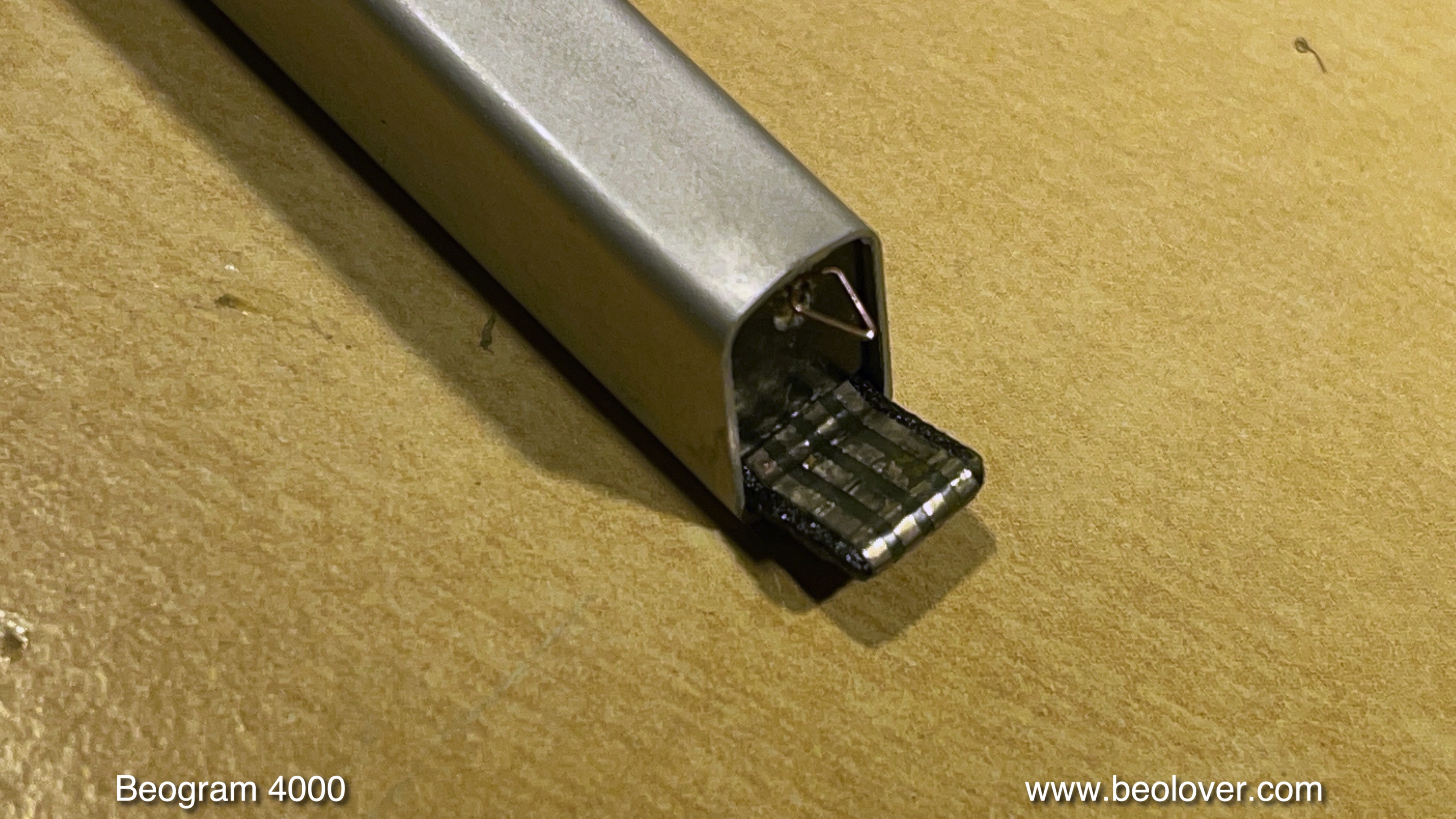
I recently received the tonearm of a Beogram 4000 located in Western Australia. Like in many Beogram 4000s the MMC cartridge mount had broken off.

This Beogram still had the 'old style' tonearm, that elegantly plugs into the base of the arm, instead of featuring soldered signal wiring. However, this makes it more difficult to replace the MMC mount since the insert that goes into the aluminum profile tube has an adapter at the rear that has spring loaded contacts that 'grab' the circuit board that reaches into the back end of the arm to make contact. This shows the sad condition of the MMC mount as received:

The first step of any MMC mount replacement is removal of the broken one. They are usually glued into the arms. Luckily, the glue softens when the arms are 'cooked' for 30 min or so. I heated this one together with the also broken one from a Beogram 4000 from the UK that I am restoring right now:

Replacement of the MMC mount is part of my standard Beogram 4000 restoration package since all mounts seem to be quite brittle at this point in time, and it is an unpleasant event if the broken off tab sticks deep in a cherished $800 rebuilt MMC20CL...This shows the liberated insert after the cooking process:
This is the 3D printed replacement part with installed flex-PCB based contact traces:
The back part with the plug-in contacts mounts onto the thin tab at the end of the part:
This shows the signal wires soldered to the new mount:
And this picture shows all the component put back together. I was able to re-use the bottom part of the mount with the grounding contact for the cartridge housing:
After checking all leads for continuity (sometimes these thin wires can be broken inside the insulation) the next step was inserting the assembly into the arm tube:
I put a bit of white wood glue on the sides of the insert when I push it in to make sure it stays put when cartridges are mounted/pulled off. The defunct cartridge makes sure that the front end components of the assembly are positioned correctly to receive cartridges without any gap between housing and arm tube:
And this shows the final result of the operation:
This tonearm is ready to travel back to Western Australia!


Monday, September 21, 2020

Beogram 4000: Replacement of Broken Off MMC Cartridge Mount with 3D Printed Replacement Assembly

I recently received the tonearm of a Beogram 4000 from Belgium. It had a broken off MMC cartridge mounting tab. Sadly, this happens to many Beogram 4000s since they used a plastic that seems to go brittle over the years. Luckily this Beogram 4000 has the old-style MMC adapter insert that connects via spring terminals to a narrow circuit board that sticks in to the arm from the back. This allows easy removal of the arm by just removing one screw and pulling it out. This shows the arm as received:


The plastic tab that inserts into the MMC cartridges is missing and only the flex PCB with the contact traces remained:

It turned out that the plastic insert was glued into this particular arm. This meant I had to simmer this arm for an hour in boiling water in order to soften the glue. After I removed the arm from the hot water I was able to push the assembly out from the back with a rod that fits snugly into the arm. This shows the extracted part:
Luckily, the lower part of the MMC mount with the grounding tab was still intact and could be reused:
The next step was to assemble the replacement part. The first step was to glue the new nickel and gold plated contact traces into the 3D printed plastic part replacement, and transfer the wires over:

Then I assembled the insert. I used a damaged cartridge for positioning the lower part with the grounding tab that it was flush with the installed cartridge. Then I glued the back part with the spring contact tabs onto the 3D printed part:
This shows the back contact tabs after assembly:

The next step was to insert this assembly into the arm in a way that the mounting screw would go straight into the back part while ensuring that the cartridge was snug with the aluminum tube. This was the result:
This is how the MMC mount looks like without cartridge:

Pretty close to the original! This arm is ready for duty again!


Monday, August 10, 2020

Beogram 4000: Replacement of an 'Old Style' MMC Cartridge Mount with a New 3D Printed Assembly

The Beogram 4000 that I am currently restoring also had a cracked MMC cartridge mount. Unfortunately, this is a problem common in many Beogram 4000 since the plastic B&O used for the cartridge mount seems to get brittle as it ages. Later Beogram 4002 and 4004 have cartridge mounts made from a different plastic, and it rarely happens that they break.

The first step was to remove the tone arm to be able to push the plastic assembly out of the arm from the back. Later 4000s have a mount that is glued in and one can remove it by 'cooking' the arm for a while in boiling water to soften the glue until one can push the mount out. More details about this procedure is posted in this blog post.

This post is about doing this replacement for an 'old style' arm, where the mount assembly is bolted into the aluminum profile of the arm. This shows the back end of the arms. The tone arm up front can be removed by taking out the screw that holds the aluminum profile to the arm base:

Then the arm can be pulled out:
Do this carefully, since there is a little spring on the excenter that allows adjusting the arm forward and backward (there is a small plate on it, that has already been removed in the above picture, but is shown in the 2nd picture below under the arm). 
Once the arm is off a small PCB is revealed that makes contact to the MMC mount assembly in the front end of the arm:
Turn the arm around, and the screw that holds the cartridge mount assembly in place can be accessed:
I removed the screw, and then carefully pushed the plastic assembly out from the back of the arm using a 8 mm diameter rod with a smooth end (to not damage the back end of the assembly) that fit into the aluminum profile. The extracted parts are shown in the upper part of the picture below:
The assembly consists of three components: (1) A 'carrier' that also has the tab (broken off) onto which the cartridge is stuck. The tab end of the carrier carries the flex circuit board that has the four traces for making contact to the coils of the cartridge (it came off due to the broken of tab). (2) A separate part that carries a grounding tab to make contact to the metal body of the cartridge, and (3) a part in the back that makes the connection to the PCB reaching into the back of the arm.
Below the extracted parts, the new plastic parts that I designed for this repair are shown. They were printed at Shapeways in black PA12 plastic, which is a sturdy engineering plastic that has a bit of flexibility while also being pretty stiff. Perfect for a cartridge mounting tab that is not supposed to break off when it is torqued a bit.

Since in this case also the grounding tab was damaged, 
I needed to design a replacement for this component, too.
The challenge was to find a suitable metal strip for fashioning a suitable grounding tab. After a bit of head scratching I had the idea to use an 'ammo pack' strip from Molex-style connector terminals:
I removed the terminals and plated the ammo strip with nickel and then with gold. Then I cut a small part off and bolted it into the 3D printed plastic part and bent the end into a suitable tab shape:
The next step was to glue a new flex PCB strip with the coil contacts (also Ni/Au plated) into the business end of the carrier part:
Then it was time to transfer the wiring:
After the soldering was done (use a small tip and be quick not to damage the plastic parts), the insert could be assembled together with the original back end part:
For assembling the ground tab part with the carrier, it is a good idea to stick a cartridge on it, which allows aligning the ground tab part with the back plate of the cartridge. I fixed the ground tab part in place with a dab of super glue gel on either side. The back end was glued on with contact cement (like in the original assembly).
And now came the interesting moment! Would this new assembly line up with screw hole in the arm tube when inserted into the tube?
Luckily it did:
While the cartridge sat snug on the end of the aluminum profile without a gap:
Perfect! This spared me another design iteration to make things match. It rarely happens that a part like this really fits on first attempt, but this time I was lucky! This shows the new cartridge mount with removed cartridge:
Beolovely! 

Time to put the arm back into its place:
A few more adjustments and it will be time to give this Beogram 4000 a first spin!


Sunday, December 10, 2017

Beogram 4000: Replacement of a Cracked Cartridge Mount with a 3D Printed Assembly

Like so many Beogram 4000s, the one I am working on right now had a cracked MMC cartridge mount. In the 4000 this part was made from a more brittle plastic than in the later 4002s, and it seems this material is not aging well. This is how this issue manifests itself:
The first step of this repair procedure is to take the arm out that the original part can be extracted. For this the screw in the back needs to be removed, and then the arm can be pulled out:
after pulling it forward a bit the part that holds the excenter down can be removed, revealing the excenter and the spring that pushes it down:
Pulling the arm further releases a spring that holds the wiring in place:
The the arm comes off and one can see the board where the wires to the cartridge mount are soldered on:
The next step was to unsolder the wires. Two of them are soldered to the bottom side of the small board:
These can be unsoldered using a mirror and carefully operating the soldering iron to get underneath from the side. After unsoldering the wires it was time to 'cook' the arm for a while to soften the glue that holds the MMC mount in place:
This one needed to be heated for an hour or so until I was able to finally push the cartridge out with a metal rod that fits into the square arm profile:
Unfortunately, this 'pushing out procedure' often results in damaged wires since there is no way to keep them out of the way while pushing the mount out from the back. In this case I had to replace two of them...this shows the 3D printed replacement part with the transferred wires soldered on:
The next step is to install the mount together with the original bottom part:
I usually glue the parts back into the arm with white wood glue (Alene's, but any other will do, too). When doing this, care needs to be taken when the mount assembly is pushed into the arm that it is inserted precisely at a depth that allows to mount the cartridge snugly. This is best done by putting a cartridge on and then pushing the mount in with the cartridge:
After letting the glue harden for 24 hrs, the cartridge can be removed:
Now the arm can be installed again:
And bolted to the carriage:
Allright! On to replacing the sensor arm light bulb with an LED assembly...