This Beomaster 4400 is opened up for restoration except for the front panel and the switch assembly.
My mechanical testing of the Beomaster switches shows there is a problem with the OFF switch where it is not disengaging selected source switches when the OFF button is pressed.
The way the switch assembly is supposed to work is for a press of one of the source switches to disengage the OFF switch and the Beomaster powers on.
When the OFF switch is already disengaged (power is on), then pressing a source switch disengages the currently engaged source switch and becomes the music source for the amplifier.
That functionality works.
Pressing the OFF switch should disengage any source switch that is pressed and the Beomaster power is turned off.
The way this Beomaster's switch panel is operating now, the OFF switch will turn the power off but the selected source switch will remain engaged.
If a repair for this function wasn't possible it wouldn't be the end of the world as the Beomaster 4400 can turn off. It would be a slight inconvenience though. For example, if you were listening to Phono and you turned the Beomaster off with the OFF switch, the Beomaster would turn off but the Phono switch would remain engaged. So if you came back and wanted to listen to Phono again you couldn't use the Phono switch to turn the Beomaster on (because it is already engaged). You would have to press a different source switch to turn power on the Beomaster, that would reset the Phono switch, then press the Phono switch.
So I am going to try and get to the bottom of the problem with this switch assembly.
Here is the switch assembly as seen from the back and still installed in the front panel.
To get to those switches there are mechanical fasteners that have to be removed (screws) and electrical connections that have to be de-soldered. Bang & Olufsen went with a lot of hard-wired connections in these 1970's era receivers. That is actually good for long term reliable component to component connections...but makes it hard to work on :-).
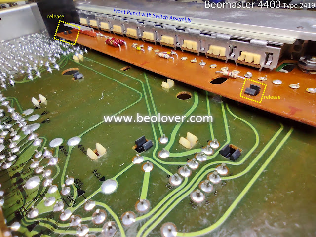
In the photo above I highlighted two plastic clips that hold and stand-off PCB 5 to PCB 6.
Those need to be released.
PCB 5 is the main board in the Beomaster. Everything connects to it.
PCB 6 is one of two signal routing boards for the switches and display components on the front panel.
Next, I loosened four screws that secure the Beomaster 4400 transformer assembly and filter capacitor bracket to the front panel. They have slots instead of holes so those pieces can just be loosened and the front panel pulled out.
Up next are four screws that attach the front panel to the frame.
Two are inside at opposite ends of the front panel.
You need a long, skinny screwdriver to access some of the screws on the Beomaster 4400.
Note the wires in the above photo. Once the panel is loosened enough to pull out, those wires will prevent being able to pull the front panel all the way off so at some point in the disassembly they will have to be de-soldered. There are too many wires to show a step-by-step de-soldering so just note that type of task has to be done at various places during the disassembly of the switch panel.
The other two screws are on the front.
The removal seems pretty easy so far but there is still a long way to go.
The next step is to do some de-soldering of some wires between the main board (PCB 5) and the switch assembly board (PCB 6).
The front panel should be able to be partially pulled away from the Beomaster 4400 at this point.
Wires from the various connections prevent it from fully coming off so those have to be tackled next.
The front panel indicator lamps need to be removed as well.
They pull off their mounting spades by carefully pulling them out. I use a small pair of pliers.
There is one indicator on the front panel, the stereo indicator, that is really a pain.
It is an LED and glued to the front panel. So it can't be removed easily and can break.
But it has two wires to it that need to be removed.
My solution is to cut the wires for the stereo indicator LED far enough back where I will add a two pin connector later.
In the past I have tried eliminating some front panel assembly steps by leaving the FM tuning dial assembly in place but that doesn't work out well.
It is much easier to get components out of the way. There are parts of the dial assembly and the flexible wire routing ribbon that are delicate so removing them also protects them.
The FM dial assembly only has two screws to remove but it also requires some de-soldering.
The next step is to remove four screws that secure the actual switch assembly to the front panel.
Once that is done the front panel should be able to be removed.
Besides the two screws the above photo shows the result of my having to de-solder a number of wires from this part of the switch panel.
The front panel should now be free to remove from the Beomaster 4400 and the switch panel will be fully revealed (well, almost).
The power cable to the OFF switch must be removed to free that connection up.
This disassembly also provides easy access to the FM signal strength meter.
It has a lamp that I will replace.
The remaining disassembly tasks are mainly de-soldering tasks.
There is the flexible ribbon that goes from the FM preset tuning dials to the switch assembly.
It is very delicate and needless to say, you do don't want to damage it.
Then there is the PCB 6 wiring board. It is soldered right to the switch assembly so it needs to be removed to be able to get to the individual switches...my goal.
One side of the switch assembly is now fully accessible.
This is the other side.
Now I can finally tend to the switches themselves.
There was a lot of de-soldering to get here. I think I had to clean my de-soldering gun twice during the process.
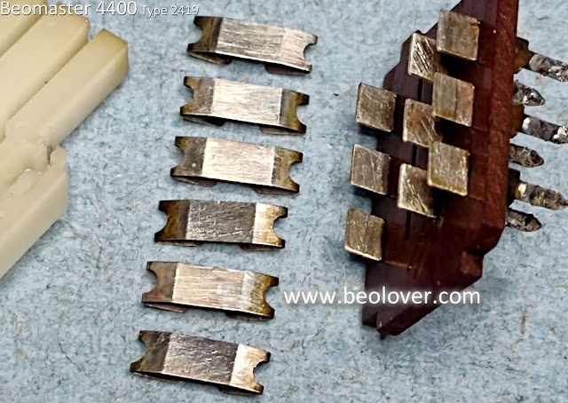
Here is one of the source selection switches (Phono switch) opened up.
The phenolic board with the contact posts slide between spring contacts in the plastic switch housing.
The phenolic board is fixed to the switch assembly frame with metal tabs.
The plastic switch is the part that moves.
One nice discovery about this earlier serial number Beomaster 4400 from the later serial numbers (that I am more familiar with) is that the tabs that secure the switches to the switch assembly frame are much longer here. It is rather easy to open these up (once you get to this point). On the later serial number Beomaster units the tabs are ridiculously tiny and terribly difficult to open up without damaging the tabs.
Here is the switch problem with this Beomaster 4400 shown with the switch assembly removed.
The picture below shows the proper switch positions when the Phono source has the Beomaster powered on and the OFF switch is in the disengaged position (meaning power is on).
Pressing the OFF button to engage it will disconnect power from the power switch and should disengage the Phono switch.
Instead, the OFF button is in the off position but the Phono switch is still engaged.
Again, that doesn't mean the Beomaster would still be powered on. It will be powered off due to the position of the OFF switch. But the Phono switch being in the engaged state will mean it cannot be selected to turn the Beomaster on again. It has to be reset to the disengaged position first.

I spent a lot of time next in operating the switches and observing how the mechanics worked.
I am convinced now that the problem is just in the action on the OFF switch as all of the other switches work properly. They engage and disengage properly when they are used.
It is just the OFF switch that is not able to reset the source switches.
Except...Tape 1. There is enough movement of the switch control bar to disengage the Tape 1 switch when OFF is pressed.
Looking carefully at the movement of the OFF switch actuator I can see that pressing the OFF button causes a small, plastic post on the actuator to push against a metal lever. The lever has a wide section and when the post press against that the lever should move the switch control bar enough to disengage any source switches that are engaged.


In the case of this OFF switch I can see that the lever is not moving enough to cause any disengage activity on the switch bar. I am able to manually press the lever a little bit more by hand and then everything worked properly.
I couldn't see any possible adjustments to make to correct the problem so I removed and inspected the OFF switch.
Interestingly I discovered a notch appears to have worn away on the small, plastic post that presses against the lever.

If it was not for that notched away section on the post there would be enough movement in the lever to move the switch bar correctly.
So that is where I will leave it for now.
I have to look at my options.
I can look for a spare OFF switch from another Beomaster 4400 of this type.
Later serial number Beomaster 4400 units are not proper donors because their switch assembly and power switch is different. Beomaster 3000 and 4000 models are supposed to share this type of switch so that is an option.
However, I want to take a stab at repairing or modifying this actuator post so that it will work.
Maybe some well placed (and formed) epoxy. I wonder if that would hold up to long term movement of the lever rubbing against it.
Beolover suggested some PTFE tubing. That might work. The post is 2 mm in diameter so I went ahead and ordered some PTFE tubing that has an inner diameter of 2 mm. The outer diameter is 3 mm so I will have to see if that will work when the OFF switch is fully engaged and fully disengaged.
Here is what the post and lever positions are when the OFF switch is engaged.
A 1 mm border around the post might be too much.
Maybe I will have to cut away some of the post material and epoxy on a 2mm outer diameter PTFE piece.
More investigation on this ahead.
While I am waiting I can get started on the capacitor replacement tasks.