The hard work restoring this Beomaster 4400 unit is starting to pay off.
I reached the milestone of reassembling the Beomaster and testing its power supplies.
In the last post the Beomaster 4400 reassembly had begun but left off needing the output amplifier transistors to be mounted on the heatsinks.
The transistors are now installed on the heatsinks with SIL pad thermal insulators.

I also wired up the power switch and mounted an arc suppression device like I usually do with these amplifiers.


The arc suppression device installation required tapping a couple of M3 holes in the Beomaster bracket that secures the large filter capacitors.
I started installing these devices after one Beomaster 4400 had arrived with severely charred switch contacts. Because these power switches can no longer be sourced (other than stealing on from another Beomaster 4400) I think it is worth a little more effort to protect them.
Before plugging in and turning this Beomaster 4400 on for the first time I plugged it in to my Dim Bulb/Variac tester.
That tester allows me to slowly apply AC power to the Beomaster while monitoring how much current it is drawing. The light bulb draws current away from the amplifier if too much is present.
Doing that protects the Beomaster from having more component damage if there is a short circuit somewhere.
Here is a good example of why it is good to start out with this type of testing.
This Beomaster started drawing too much current right away as I dialed up the AC voltage on the variac.
It reached about 400mA by the time I was at 50 V.

I stopped and removed power.
After going over the wiring of the Beomaster I found and fixed the problem.
Running the test again I now have a clean power up of the Beomaster unit.

Around 260 mA with full input power applied.
That matches what I get with other Beomaster 4400 units.

Here are the +15 V and +35 V reference voltages.


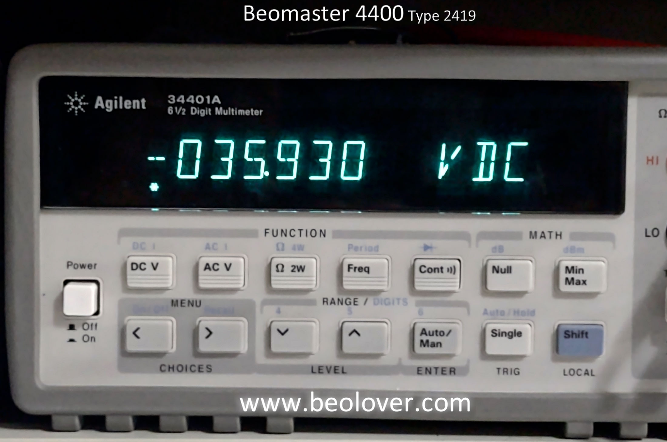
Next is the -12 V reference for the audio muting circuit.


Here is the reference voltage for the Phono, Tape 1 and Tape 2 preamplifier circuits.


Here are the 24 V Left and Right channel reference voltages for the preamplifier tone controls.


Here are the power amplifier positive and negative rail voltages.


Finally, here are the Left and Right channel no-load current checks and adjustments for the output amplifier.
The service manual says to measure across the emitter resistors and adjust for between 10 mA and 15 mA.
For now I will roughly set them above 10 mA. I will adjustment them more precisely later. Probably at 12 mA.


It feels great to finally have this Beomaster 4400 amplifier powering on again.
In the next post I will start in on some bench testing that is include some actual music listening tests.
No comments:
Post a Comment
Comments and suggestions are welcome!