It is time to get cracking on a delayed Beogram 4004 project.
I initially assessed this Beogram 4004 back on this January 2022 post.
A bunch of delays ensued but now things can get moving again.
I disassembled the Beogram 4004 to begin work on the various components.
Here is the PCB 1 board shown with its four mounting screws highlighted.

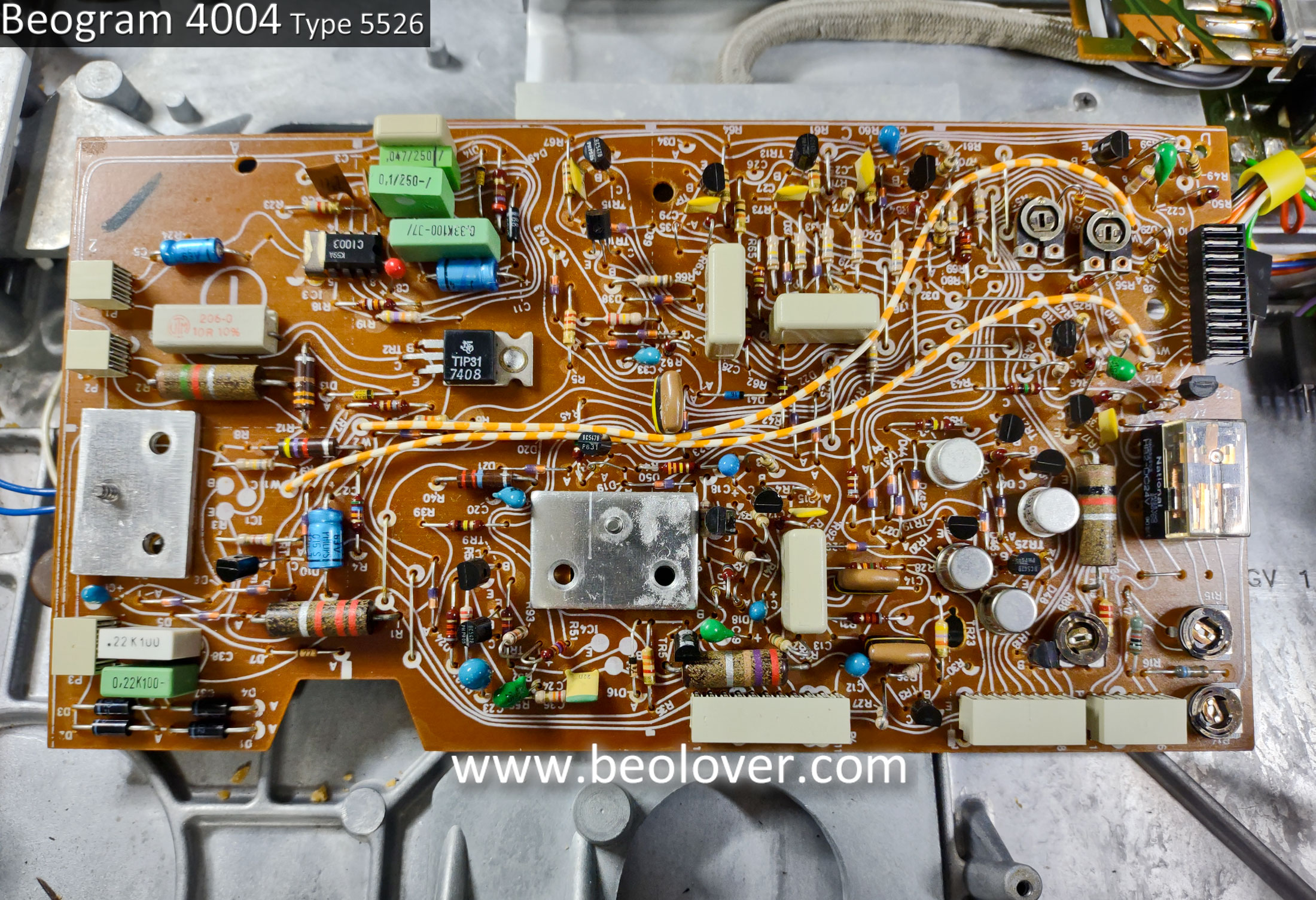
Here is PCB 1 removed. The main circuit board, PCB 1, looks in great condition so I will start on the restoration of this board in the next post.
Next in line for the disassembly is the Beogram keypad.
This keypad is in really nice shape for an original keypad. There are some minor scuffs and with the light held just right, you can see some signs of where fingers operated the controls.

The underside of the keypad shows the typical tarnished button contacts. I will clean those thoroughly and coat them with some Deoxit contact cleaner.

With the keypad removed I can get to the Beogram 4004 Output/Remote Control board (PCB 8).
The PCB 8 board contains the phono mute relay and is where the audio signal transitions from the tangential arm assembly chassis to the phono cable that carries the audio signal to an external preamp.
Here is PCB 8 from this Beogram 4004 unit.

PCB 8 is a board that is in all Beogram 4002/4004 turntables. All of the types have the Phono Audio Output and Mute circuit. The rest of the PCB 8 board is for additional circuits that various Beogram 400x types can have.
For example, the Beogram 6000 has 4-Channel decoding circuitry on its Output Board.
The Beogram 4002 Type 5523 only has the muting circuit and nothing else.
This Beogram 4004 has a remote control circuit that integrates with the remote control of the Beomaster 2400 receiver. Of course nowadays we have the Beolover Commander Remote Control. :-)
After PCB 1, PCB 8 and the control keypad components are out of the way, the Beogram 4004 floating chassis can be removed from the cabinet base.
This photo shows a section of the cabinet with one of the lockdown mechanisms for the floating chassis. There are three of these lockdown mechanisms and each one must be disassembled to remove the floating chassis. The original Beogram 4004 would have had rubbery, plastic bushings around the lockdown plates. As is very common, the original bushings became hard and brittle...to the point where they just broke into pieces.
This photo shows a section of the cabinet with one of the lockdown mechanisms for the floating chassis. There are three of these lockdown mechanisms and each one must be disassembled to remove the floating chassis. The original Beogram 4004 would have had rubbery, plastic bushings around the lockdown plates. As is very common, the original bushings became hard and brittle...to the point where they just broke into pieces.

The following photos show the disassembly of the top part of the floating chassis lockdown mechanism.


This picture shows a lone piece of the original lockdown bushing. That is where the bushing was located before it deteriorated and broke apart.

Here is the lockdown mechanism after the floating chassis has been removed.

Here is the removed Beogram 4004 floating chassis assembly.
Highlighted in the photo is the actuator of the Beogram ES switch. It was floating around in the cabinet.

The tonearm assembly looks really great on this Beogram 4004 unit. The arm lowering works nice and the components look to be aligned properly.

The servo motor and pulley look okay and do function.
The original plastic pulley is in good shape but does have the start of a small crack.
The internal vibration damping material of the servo motor is showing signs of age. The foam material eventually crumbles and becomes dust.

Here is a picture of the SO and ES switches of the Beogram tangential arm assembly.
The ES switch is broken and the SO switch looks pretty worn too.

Here is what two intact SO and ES switches should look like.

I will have to find a couple of replacement switches for the ES and SO switch.
Last, here is a look at the tonearm assembly lowering and raising mechanism. It is in great shape as I mentioned earlier.

After this Beogram disassembly I can update my assessment of the restoration.
The recapping and replacing of components on the circuit boards doesn't appear to have any surprises.
I have all of the parts I need so those tasks can begin right away.
The keypad just needs some cleaning of the switching contacts.
The floating chassis needs new lockdown bushings.
The servo spindle pulley may need replacing with a new aluminum pulley. I will further evaluate the condition of the plastic pulley.
I will also check the servo motor vibration damping material to see if it needs new material.
The ES and SO switches need replacing. I should be able to source those myself.
On to the circuit board work ...
No comments:
Post a Comment
Comments and suggestions are welcome!