Featured Post

Beolover SyncDrive: DC Platter Motor Replacement for Beogram 4002 and 4004 (Type 551x and 552x)

Late Beogram 4002 and the 4004 (Types 551x and 552x), which have DC platter motors instead of the earlier synchronous AC motors usually suff...

Showing posts with label grounding switch. Show all posts

Thursday, December 27, 2018

Beogram 4004 Type 5526: Recapping the boards on the second Beogram 4004 from Texas

I removed all of the components that were necessary from the Beogram cabinet to clean out all of the debris from the old transport bushings.


The cabinet is now ready as I work on the individual components.

I decided to tackle the recapping of the two circuit boards first.
Here is the main (controller) board before the recapping. Note that the RPM relay on this Beogram controller board is the National type of relay. It has a different footprint than the Siemens relay used on the first Beogram 4004 I restored. Beolover's replacement relay assembly comes in both sizes so that isn't a problem. You do need to check that before ordering a replacement relay for your project.


Here is the output board. It also has the National type relay. So far I have found that whichever type of relay (Siemens or National) is used it will be on both boards.


On the recapping of the controller board I replaced all of the electrolytic capacitors and tantalum capacitors with 105°C, Japanese electrolytic capacitors or WIMA MKS capacitors. The two trimmers for the 33⅓ RPM and 45 RPM platter speed calibration were changed to sealed, multiturn type trimmers. I also changed capacitor 1C10 from the original 0.33uF to 10uF. The reason for that is because the stability testing on the DC platter motor after Beolover's restoration process showed that the 10uF value provides more stable speed results.

Here is the recapped controller board.


On the output board I also replaced the electrolytic and tantalum capacitors with 105°C Japanese electrolytic capacitors and WIMA MKS capacitors. The muting relay was traded out for the Beolover replacement relay and our usual grounding switch was installed. The grounding switch provides more options for the phono cable connection to non-B&O preamplifiers. In most cases it eliminates the need for the extra, external grounding wire from the Beogram to the preamplifier.


Both boards are ready to use.

Monday, May 14, 2018

Beogram 4002: Final Tasks, Adjustments & Playing Records

It is time to finish up this Beogram 4002 Type 5513 project. As a continuation of the corrosion damage repair I am replacing the 5-pin DIN phono plug.

Here is a nice reference diagram Beolover created a while back that shows the audio path from the MMC cartridge connector to the 5-pin DIN plug.


I like this diagram because when I am replacing the phono cable plug this shows the phono signals I check continuity on from the Beogram output board connector (P9) to the front of the plug.

Here is a picture of a continuity check for the phono right channel from the phono DIN plug to the output board P9 connector.


I installed a REAN 5-pin DIN replacement plug that has gold contact pins.


A note to other DIY folks that do this - Some of these Beogram phono cables have a cable diameter that makes installing the REAN rubber boot extremely difficult. The fit is really, really tight.

Another phono signal related change I made was to return to the output board and install a grounding switch between pins 5 and 6 of the P9 connector. That is signal ground and shield ground respectively. The Beogram 4002 units come with a separate grounding wire so owners can connect their Beogram chassis ground to an amplifier's chassis ground should there be hum in the signal path.
This grounding switch eliminates the need for that extra grounding wire as the switch can be flipped to short the two grounds together in the Beogram if needed. A nice option and the switch is easy to get to.


One last electrical task is to install the two RPM indicator light replacements (33 & 45 RPM lights). This upgrade of incandescent lamps to the Beolover LED replacement is not for cosmetic reasons. Beolover's ongoing testing of Beogram 4002/4004 DC platter motor stability has shown a positive measurable effect of the LED lamp assemblies over the incandescent lamps. So we recommend them on all of our Beogram 400x restorations.


One weak part of the Beogram 4002 design are the mounting clips for the RPM indicator panel into the control panel. The mounting clips are a hard plastic that often becomes brittle over time and cracks. This unit had a couple of hairline cracks so I applied some preventative patches.


I started the final reassembly of this Beogram unit which includes the service manual adjustments.

The first adjustment is for the Beogram platter height so that the distance from the top of the fixed arm (and tonearm) is 23mm from the surface of the platter. That adjustment is made using the large nut on the platter hub.


The tonearm lowering limit and pickup arm length adjustments are next.


That is followed by vertical and horizontal arm parallelism.


While the platter belt is still removed I adjusted the tangential arm sensor.


Now for the deck panels and the platter position adjustments.


Everything looks good. I performed the arm balancing adjustments earlier so the final adjustments are for the platter speed trim pots.


This Beogram is cleared for record play. I'll give it a listen as I document this blog post :-).


It looks like this Beogram is ready to go back home to Houston. Now where's my copy of "Houston El Mover"?


Saturday, July 15, 2017

Beogram 4004 Type 5526: Tonearm Lowering Damping

The tonearm lowering on the Beogram 400x turntables is accomplished by a solenoid that engages/disengages per an electrical control signal. When the solenoid engages, the tonearm is free to lower. To prevent a straight drop of the stylus onto the record there is a damping piston that slowly lowers the tonearm.

On these Beogram 400x turntable restorations we always service the arm lowering mechanics to make sure it is operating correctly and continues to operate correctly.

This picture shows the arm lowering components before I worked on them.


There are just four screws to remove and two springs to detach in order for the arm lowering damper to be removed for service.


There you have it. The Beogram 4004 arm lowering mechanics removed for servicing.


The damping piston valve control is opened up (I remove it) and the piston pulled out of the tube.


Everything is wiped down then lubricated again before re-assembly.

Here are the lowering components re-installed. Pulling on the solenoid engage lever manually allows me to check the piston control valve and adjust it so the tonearm lowers to play position in about one second.


While the tangential arm components are removed from the chassis I will do more cleaning and lubricating. I will also change out the stationary arm lamp and sensor with the custom Beolover replacement part.

Before I get to that though, I was not completely happy with the installation of the optional phono grounding switch on the output board. A nice thing about having pictures to document a restoration is that I can review them and evaluate the results of my work.

On this Beogram 4004 output board I felt the need to use hot glue to secure the optional grounding switch. Without something to secure it the switch was wobbly. The 1M ohm trimmer resistor on the board takes up too much space to allow me room to install the switch the way I would like.


You can see the glue doing its job in the above pictures. Not horrible but I don't like the look.
I decided to go back and rework this installation. I changed out the 1M ohm trimmer resistor with one that has a smaller footprint (setting the resistance value to what the original setting was).

The new trimmer resister gave me enough space to install the switch better so that I don't need any hot glue. As you can see below the black hot glue peeled right off and is gone now. I like this version of the installation much better.


Thursday, July 13, 2017

Beogram 4004 Type 5526: Output Board Recap and Update

The Beogram 4004 output board has the usual phono signal connector and muting relay but also has circuitry added to allow remote control functionality from a Beomaster such as the Beomaster 2400. For this board I replaced the two electrolytic capacitors with new ones and the two tantalum capacitors with WIMA MKS capacitors. I replaced the muting relay with a new, sealed Omron relay mounted on Beolover's custom adapter (so that it is directly replaceable with the original National relay).


As Beolover typically does I added an optional phono cable grounding switch to the output connector. This switch allows an owner to connect the phono signal shield wires to the Beogram chassis ground or leave them open (as they normally are). The normal configuration is fine when using the Beogram phono DIN connector with a B&O Beomaster (like the 2400). However, when connecting the phono cable to a non-B&O amplifier there is often hum present that requires connecting an extra grounding wire from the Beogram to the amplifier chassis ground lug. This grounding switch eliminates the need for the extra grounding wire.

While the small switch is secured by the leads soldered to the board, I added black hot glue around it to give it extra support. I like that glue for this application because it will provide the needed support but isn't permanent like epoxy glue. The black hot glue can be peeled off in the future if so desired.


This board is a quick task so it is on to turntable mechanical parts for cleaning, lubrication and adjustment.

Saturday, July 1, 2017

Beogram 8000: Final Steps

I was kind of lucky I suppose in finding the intermittent pause culprit on the first suspect. However it was the most likely when reviewing the problem. Even though the behavior was intermittent it lined up with a problem Beolover had on a Beogram 8002 project earlier. After replacing the Beogram 8000 original control panel board with one of my spares -


the result has been over twenty error-free record plays.

Returning to the original control panel board to look at repair options I examined the LDR (photoresistor) devices for the forward and reverse controls.


Visually examining them and testing their resistance with different light sources didn't reveal any problems. These devices can become unreliable over time and exhibit the intermittent behavior I experienced so I decided to apply the repair Beolover did on the Beogram 8002.

I ordered the same LED from Newark and some GL5549 LDR devices from a couple of different sources. Replacing the original lamp with an LED requires a load resistor so I used the 1K ohm value Beolover had set his to.


Using the same parts I was hoping the fix would just be a quick install, test and go operation. Unfortunately I found that these GL5549 LDR devices vary in performance by quite a bit. It took quite a while to find a pair of these new LDRs to match and be around 20K ohms when in place on the board.

After finally finding a couple of acceptable LDR devices to try I mounted them with some temporary glue to secure them in their respective mounting slots.


I prepared the control panel board for re-installing into the Beogram. That included adding my little LDR test connector. This time I used 30 gage hook-up wire so the test connector can be left in the control panel. I matched the wire colors to what the Beogram 8000 colors are for the LDR measurements. That makes it easier to remember later if I have to retest the LDR voltages.


The connector is also a female connector so I don't have to worry about anything shorting by it when I leave it in the Beogram.

Testing the reworked control panel board with the new LDRs was interesting. I ended up having to re-adjust the position of one of the LDR devices. That is why I use glue that isn't permanent. Eventually I was able to get the forward and reverse LDRs adjusted within the 600mV - 700mV range necessary for successful operation. The service manual originally asked for 620mV but later updated that value to 650mV. I talked to another Bang & Olufsen technician who told me a solid value between 600mV and 700mV is sufficient.


As you can see in the picture above, the adjustment for a working forward and reverse operation resulted, again, in quite an imbalance in the adjustment screws of the control panel board. The voltages are stable though so I am going to run another play test with this board just to see what happens.

For this project though I am inclined to go with the replacement control panel board that I ran the twenty successful record plays with. The forward and reverse LDR controls are closely matched on that board and I feel will be more of a sure thing. This replacement repair is looking good but I will feel better about it if I can do a long term test with it.

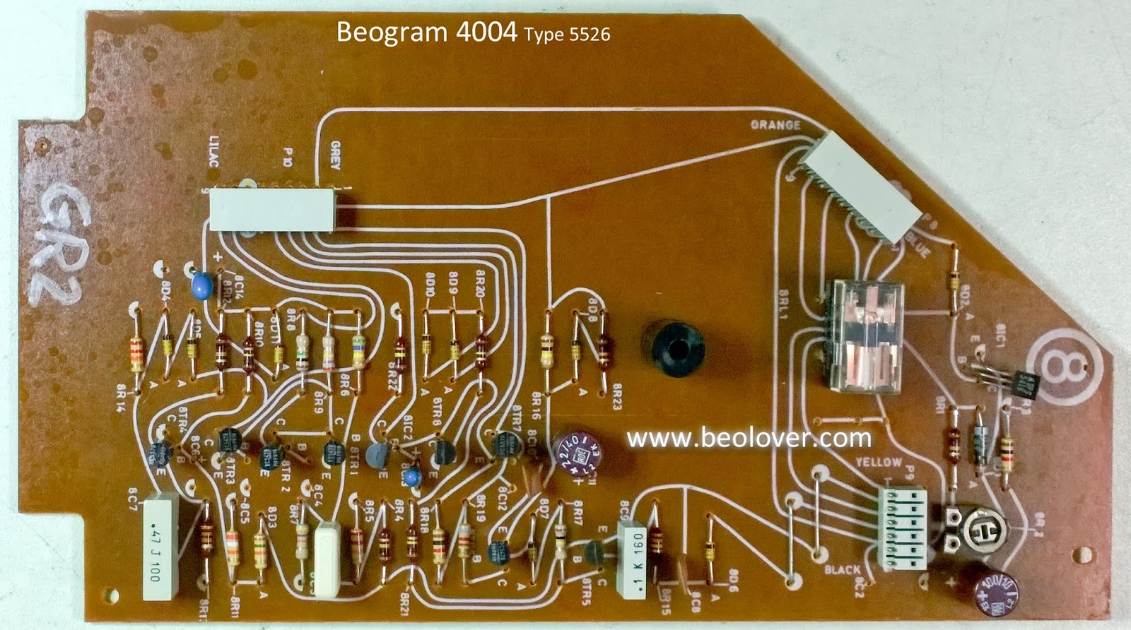
There is one more issue that cropped up during the play testing of this Beogram 8000. Another intermittent problem but one that was easily recognized. A couple of times after a record completed play I noticed that the phono mute did not occur. That means the Beogram phono mute relay is acting up. This picture shows where the muting relay is located. It is easy to get to but does require opening up the Beogram case again. Oh well.


I hadn't planned on replacing this relay but since it has come up I asked the owner if he would like the phono grounding switch to be added. This is a convenience option that Beolover has been doing on Beogram 400x and 800x turntables. The added switch gives a user the option of setting the turntable up as it is originally or shorting the phono signal ground to the Beogram chassis ground.

This is a nice feature for Beogram owners that use the turntable with a non-B&O amplifier. I pair a lot of my Beogram units with my Yamaha C2a, C2x and C-70 preamplifiers. Those pre-amps support two turntable inputs but require using RCA jacks. When I add the DIN to RCA converter I get a hum in the phono signal unless I attach an extra grounding wire on the adapter to the amplifier chassis ground lug. With this switch added to the Beogram I can short the phono signal grounds to the chassis ground in the Beogram and not need the extra grounding wire on the cable adapter.

It's doesn't seem like a big deal but it is nice to have options so we are adding the switch to this Beogram.

First I need to removed the faulty muting relay.


This muting relay is different than the one in the Beogram 8002 turntable where Beolover was able to replace it with a new Omron sealed relay device. That relay pin layout is not a match for this Beogram 8000 output signal board. My only option here is to take a newer output relay from one of my later model Beogram 8000 spares.


If I didn't have a spare I would have removed the clear plastic cover and tried to clean the relay contacts. That still might not have solved the problem if it is in the relay coil.

I installed the new muting relay and then attached the grounding switch.


I used some hot glue in the gap between the output board case and the switch case. This helps secure the switch.

Now it is back to the record play testing again. Success of these tests will result in this Beogram being packed up to return home.