Featured Post

Beolover SyncDrive: DC Platter Motor Replacement for Beogram 4002 and 4004 (Type 551x and 552x)

Late Beogram 4002 and the 4004 (Types 551x and 552x), which have DC platter motors instead of the earlier synchronous AC motors usually suff...

Showing posts with label project start. Show all posts

Tuesday, July 4, 2023

Beomaster 1900 Type 2904: Assessment of a New Beomaster Restoration Project

Here is the start of a new Beomaster 1900 restoration project. 

This Beomaster unit has been patiently waiting for me to retool my workshop for Beomaster restorations after a lengthy stint of Beogram restorations and repairs.

I have several different Beomaster units in my backlog at the moment and it is time to start getting them working again.

So here is the first look at the latest Beomaster 1900.


The Beomaster 1900 is in really nice cosmetic shape.  I would rate it excellent except that it is suffering from a common problem with these models.  The thin veneer trim is separating from the plastic side panels the trim is mounted to.  I have seen this before with the Beomaster 1900 and 2400 receivers.

The plastic side panels and single, front panel do remove from the cabinet though.  Removing them (carefully so as not to break their mounting tabs) will make it easier to fix/reattach the veneer.

I moved on to the disassembly of the Beomaster so I can prepare it for replacing the electrolytic capacitors inside.  There are quite a few electrolytic capacitors to replace.  Around seventy.

I started removing the panels of the Beomaster 1900 first.

This photo shows the control panel (with the touch buttons) and the front, plastic trim piece removed.


The next four photos show removing the Bass, Treble and Balance indicator masks from the slide controls so the control panel PCB can be removed.

I was happy to see that the indicator masks were is great shape and the slide controls appear to be intact and working.


Two press-to-fit connectors are all that connect the control panel PCB to the rest of the Beomaster components.  I disconnected those and removed the control panel PCB.


With the control panel PCB out of the way I continued on and removed the indicator panels (the volume indicator, the Bass, Treble and Balance indicators and the source selection indicators).

Here is the volume indicator panel being removed.


Here is the indicator panel for the Bass, Treble and Balance being removed.


Finally, here is the source selection indicator panel shown already removed.


Here are the two plastic side panel (trim pieces) removed.


In order to free up the main PCB I removed the four output amplifier transistor heat sink assemblies.


I cleaned off all of the old white thermal paste from the transistors and heat sinks.
I will be replacing the thermal paste with SIL-Pads.

The Beomaster 1900 is now in a position where I can access all of the electrical components I need to access in order to start replacing old capacitors.  A while back I started making the parts for a jig to support the disassembled Beomaster 1900/2400 structure.  I used the pieces I have completed so far to put the Beomaster 1900 into a service position for working on.





Saturday, January 15, 2022

Beomaster 4400 Type 2419: A Project from Austin Texas

The workbench is full now...with this addition of a Beomaster 4400 restoration project.
This Beomaster was delivered to me by its owner from Austin, Texas.
Not as close as the owners of the Beogram 4004 and Beomaster 2000 projects but close enough to not have to ship the unit.

The Beomaster 4400 is one of my favorites so I am always glad to get a chance to restore one.
My only real fear on these type of restorations is what condition the front switch panel is after 45 years (B&O started producing these in 1977).

These Beomaster 4400 amplifiers are really good in driving a pair of Beovox M100's, M75's or MS150's.
I use my Beomaster 4400 with a pair of MS150.2 speakers and the sound is wonderful.

Here is the Beomaster 4400 subject for this project.


It has some issues with the slider control lenses but a lot of these Beomaster 4400 units do.
A lot of the time the lenses have become discolored and cloudy.

On this Beomaster the problem is the lenses are scratched and worn.
I have a replacement set of lenses from Beoparts ready for them though.


The Beomaster 4400 is also missing the cover plate for the FM preset switches.
I have a replacement part for that too.

The front panel switches appear to operate okay but the Off button doesn't force all of the input source switches to switch off when the Off button is pressed.  I will have to investigate the switch panel to resolve that.  It is the one task I would prefer not to have to do.


The under side and rear of this Beomaster looks good.  I don't see rust and corrosion like I have seen on poorly stored units.  I think this Beomaster must have been stored in a good location.
I will find out more when I open up the receiver.


The serial number is quite faded but I think I can make it out to be 1510043.


I will assess the restoration tasks on the inside of the Beomaster 4400 in the next post.

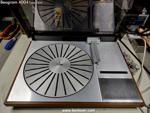
Beogram 4004 Type 5526: A Local Beogram 4004 Project Begins

I have been fortunate to have restored quite a few vintage Bang & Olufsen audio components for original owners. I like that because they remember what these components were like brand new and are the ideal judge for a restoration project.

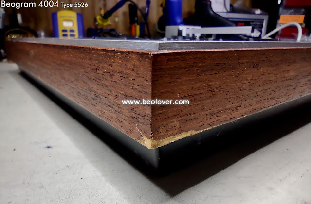
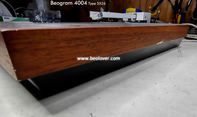
This Beogram 4004 looks to be in great shape although it doesn't have a couple of nicks in the plinth wood trim.


The button control panel has the expected wear on the button panel surface.  


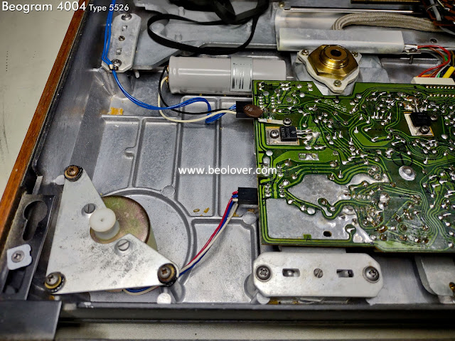
The inside is very clean as I would expect from an original owner's Beogram.
I do see some debris from deteriorating suspension transport lock bushings. That is also expected as we see that on almost every Beogram 400x turntable.


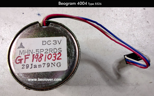
I pulled out the platter motor of course and sent it to Beolover for a full restoration of that component.


The restoration plan to start with is to focus on returning this Beogram to perfect functional condition.
Along the way we will decide how much restoration we will do on the cosmetic condition of the turntable.  That is an advantage for a local owner as shipping is not involved with this unit.  A restoration can be done in more than one visit to the workshop :-).

Beomaster 2000 Type 2801: A North Texas Beomaster Project

This is an exciting first blog post of a Beomaster type I haven't seen before (other than photos).

A very clean and beautiful Beomaster 2000 Type 2801 from the mid-seventies.


It is quite long compared to other Beomaster low profile receivers.
Here is it is next to another restoration project I am starting...a Beomaster 4400.


...and I thought the Beomaster 4400 was long.

The Beomaster 2000 also has a tilt stand to really show it off.


Slide out panels on the left and right sides of the control button section hide the Loudness button, Tape selection and the FM radio presets.


The Beomaster arrived with a European type power plug but it has multiple power selections available so I will use 130 for the USA and change the plug to one for our receptacles.


I will have to continue the initial assessment of the restoration tasks in the next post when I open up the Beomaster 2000 and take a peek inside.

Tuesday, July 13, 2021

Beogram 8002 From North Texas: Project Assessment

Today is the start of another Beogram 8002 (Type 5633) restoration project.  The owner doesn't live too far away so no boxing and shipping was necessary.  Just a lock down of the floating chassis screws and the Beogram was delivered.  I like when that happens.

This Beogram 8002 is the usual USA type (5633) with the rosewood trim.


Although a little dusty, this Beogram 8002 appears to be still intact with its original parts.
The main aluminum deck panel looks like it was already re-attached by somebody though.
Same for the aluminum lid over the tonearm compartment.

The dust cover and tonearm compartment lid assemblies share a hinged panel and that piece was already off.


Three of the four plastic mounting clips for the back panel (highlighted in yellow) are broken off (missing).  The fourth one is intact.

The fixed bracket where the dust cover lowering mechanism attaches to the dust cover is coming loose. It still has the original Bang & Olufsen mounting tape that is now deteriorating.


That will have to be removed, cleaned up and re-attached.

This photo shows the tonearm compartment deck cover in two pieces (outlined in red). The original B&O tape deteriorated as usual on that piece so it will have to be cleaned off and put back together.
The two green outlined areas show that the deck and tonearm compartment lid are already securely attached.


Inside the Beogram 8002 all of the components look to be original and in good shape.  A good starting point for the restoration.


The main circuit board and the transformer assembly are intact.
I do see something interesting with the circuit board though....There should be a little post on the Beogram frame and a slotted rubber grommet that keeps the main board securely in place. That post is broken on this Beogram and the grommet nowhere to be found.

I will have to see if I can make some sort of replacement that will do the job of securing PCB 1 to the frame.


The PCB 1 board itself looks all original.  That is always good.


The same is true for the control button panel.  It looks to be in really good condition.


The only notable issues I found with this Beogram 8002 are the back panel for the dust cover (missing mounting tabs) and the missing mounting post on the frame for securing the main circuit board.  I don't regard either of those issues as anything major to overcome and I expect to have this Beogram back to like new condition.

Thursday, June 3, 2021

Beogram CD50 From North Carolina: Changing the CD tray belt

The problems with the CD tray on this CD50 unit point to a problem with the CD tray rubber belt. The CD50 has a gear assembly that is driven by a single rubber belt that connects to a DC motor.  It is highly likely that the belt is broken.

The belt replacement on the CD50 is not something that can be done in 5 minutes by its owner.
As nice as these CD players are they require quite a bit of disassembly to get to the CD tray drive belt.

I started out by removing a single screw that connects the front cabinet lid to the front of the CD tray.


I am not going to show a step by step removal of the CD50 inner parts but I will show a few of the key steps to get to the belt.

After freeing up the CD tray from the front of the cabinet I cleared space behind the CD tray (and laser assembly) so I could move them out of the way and expose the gears involved with the CD tray belt.


There are four screws that must be removed to allow the laser assembly to be lifted off the CD tray assembly.


Once the laser assembly is lifted out of the way the CD tray belt should be visible.
The following photo shows where the belt should be but there is no belt visible.


Looking closer my worst fear regarding the belt is realized. I can see remnants of a deteriorated belt.


It wouldn't be too bad if the repair task for this type of belt failure was just to gather the broken belt pieces and throw them away. Instead, these belts begin to deteriorate into a sticky, black, glue-like substance that sticks to everything. The rubber has broken down in a way where it doesn't dry out. It remains soft and sticky. It is a real pain to clean up. The only way to remove it is to wipe it off with Q-tips, cleaning pads and isopropyl alcohol.

To make the problem worse, the belt originally broke into multiple small pieces so the gooey substance is in various places inside the CD50.

All along one side of the CD tray slide.


Here is a better look at what the residue looks like up close.


It took a lot of searching for belt debris but I believe that I finally got all of the belt residue removed.


The pulley on the CD tray drive motor is clean and ready for a new belt but the attachment of the other end of the belt requires more disassembly.

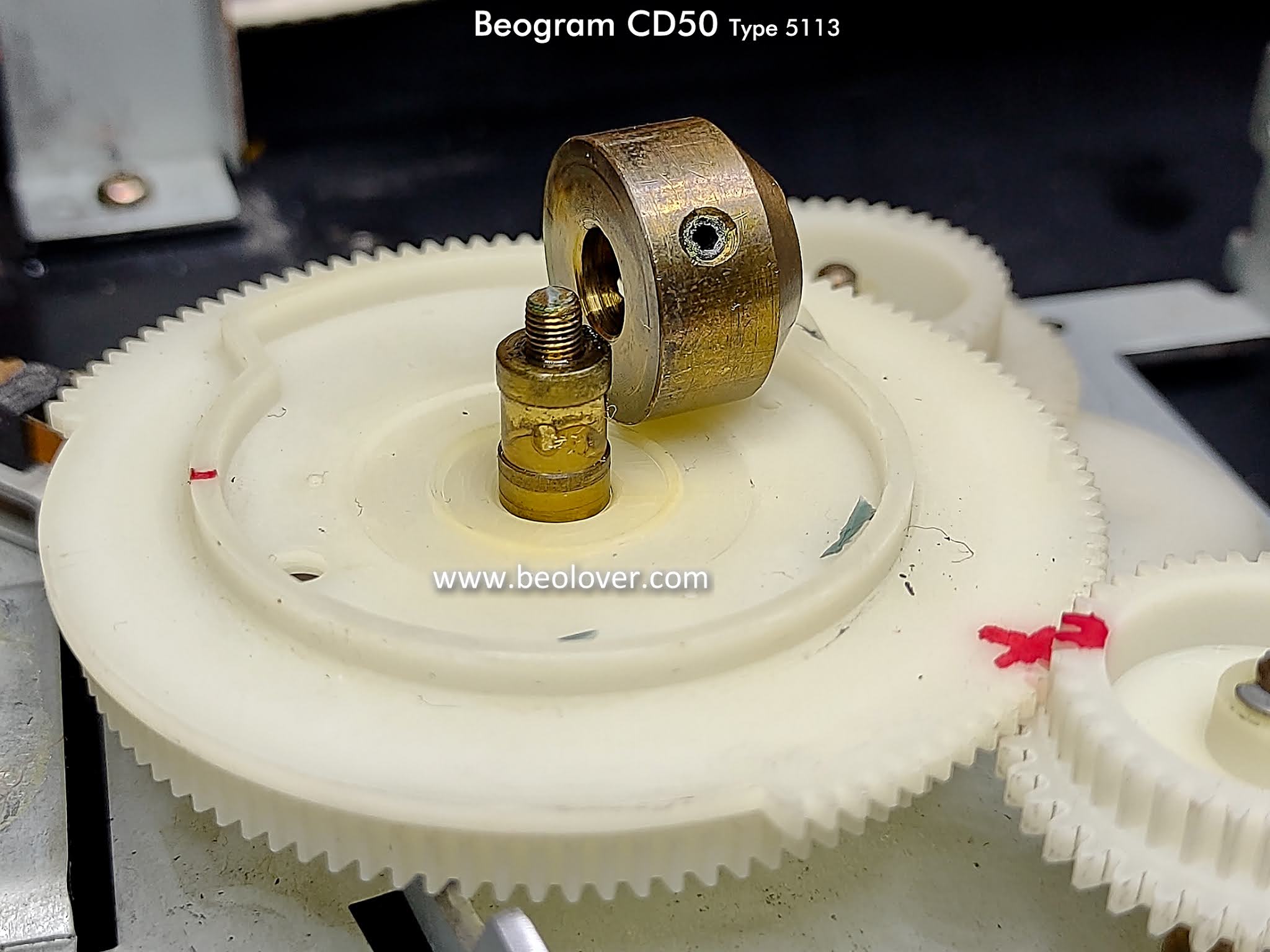
The CD tray drive mechanism has a plastic gear assembly that must be disassembled.

The first step in disassembling the gears is to mark their starting positions.  The gear pieces must be assembled with the correct orientation in order for the drive system to work so marking the positions before removing anything will insure that the pieces can be easily reassembled later.


The next sequence of photos are a step by step removal of the CD tray gears in order to get to the gear/pulley for the CD tray belt.


When I tested rotating the pulley the belt attaches to I noticed a lot of resistance. It is just over a metal post so it should turn easily. 

I pulled the gear/pulley off the post and immediately saw more of the black, goo, belt residue underneath. It was causing some significant damping to the rotation of the gear.


I did some more cleaning and finally got rid of all the troublesome belt residue.


Now I could finally install a nice, new CD50 belt sourced from Martin Olsen's Beoparts store.


The new belt is installed.  I can move on to the next step in this CD50 restoration.