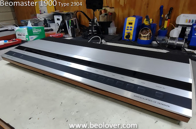
Here is the start of a new Beomaster 1900 restoration project.
This Beomaster unit has been patiently waiting for me to retool my workshop for Beomaster restorations after a lengthy stint of Beogram restorations and repairs.
I have several different Beomaster units in my backlog at the moment and it is time to start getting them working again.
So here is the first look at the latest Beomaster 1900.
The Beomaster 1900 is in really nice cosmetic shape. I would rate it excellent except that it is suffering from a common problem with these models. The thin veneer trim is separating from the plastic side panels the trim is mounted to. I have seen this before with the Beomaster 1900 and 2400 receivers.
The plastic side panels and single, front panel do remove from the cabinet though. Removing them (carefully so as not to break their mounting tabs) will make it easier to fix/reattach the veneer.
I moved on to the disassembly of the Beomaster so I can prepare it for replacing the electrolytic capacitors inside. There are quite a few electrolytic capacitors to replace. Around seventy.
I started removing the panels of the Beomaster 1900 first.
This photo shows the control panel (with the touch buttons) and the front, plastic trim piece removed.
The next four photos show removing the Bass, Treble and Balance indicator masks from the slide controls so the control panel PCB can be removed.
I was happy to see that the indicator masks were is great shape and the slide controls appear to be intact and working.
Two press-to-fit connectors are all that connect the control panel PCB to the rest of the Beomaster components. I disconnected those and removed the control panel PCB.
With the control panel PCB out of the way I continued on and removed the indicator panels (the volume indicator, the Bass, Treble and Balance indicators and the source selection indicators).
Here is the volume indicator panel being removed.
Here is the indicator panel for the Bass, Treble and Balance being removed.
Here are the two plastic side panel (trim pieces) removed.
In order to free up the main PCB I removed the four output amplifier transistor heat sink assemblies.
I cleaned off all of the old white thermal paste from the transistors and heat sinks.
I will be replacing the thermal paste with SIL-Pads.
The Beomaster 1900 is now in a position where I can access all of the electrical components I need to access in order to start replacing old capacitors. A while back I started making the parts for a jig to support the disassembled Beomaster 1900/2400 structure. I used the pieces I have completed so far to put the Beomaster 1900 into a service position for working on.


No comments:
Post a Comment
Comments and suggestions are welcome!