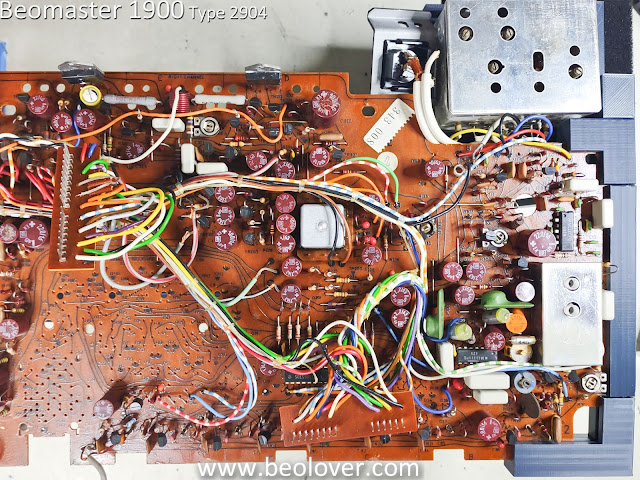
The capacitor replacements have been made to the Beomaster 1900 main PCB and Volume Control PCB.
There were quite a few. Sixty-four capacitors so far. eleven were tantalum type capacitors while the rest were electrolytic capacitors.
Here are some photos of the Beomaster main PCB before any capacitor replacement.
As I removed the old capacitors I measured them out of curiosity regarding how out of tolerance the capacitors were.
Here is a sampling of how the old capacitors measured.
Even the tantalums were either out of tolerance or right on the edge.
On the Beomaster 1900 and 2400 restorations I like to start the capacitor replacement with the two 5000uF filter capacitors for the ±31 VDC rails. They are the most difficult because of the number of wires the B&O design connects to them.
The rest of the capacitor replacements are just de-soldering two leads for each old capacitor and then soldering in the two leads of replacement capacitor...respecting their polarity of course. There are just a lot of them. Replacing the capacitors that are smaller values with WIMA MKS non-polar capacitors makes the job a little easier.
Here is a picture of the Volume Control PCB recapped.
Here are pictures of the main PCB recapped.
...and last, here is a picture of the recapped main PCB with the 64 replaced capacitors.
I still have a few capacitors to go. They are located on the tone control panel. Those will be next.
I also need to replace the no-load current trimmers for the output amplifier and I plan to change out the bridge rectifier for the 15 VDC supply.


No comments:
Post a Comment
Comments and suggestions are welcome!