Featured Post

Beolover SyncDrive: DC Platter Motor Replacement for Beogram 4002 and 4004 (Type 551x and 552x)

Late Beogram 4002 and the 4004 (Types 551x and 552x), which have DC platter motors instead of the earlier synchronous AC motors usually suff...

Showing posts with label SN04181953. Show all posts

Tuesday, June 29, 2021

Beogram CD50: Typical Restoration Steps

 After my recent posts of a Beogram CD50 restoration I opened up and restored two of my own CD50 units. The CD50 in the earlier blog posts was a later model than both of mine. It is serial number 4181953 while mine are 3449007 and 3293019.

My SN:3449007 CD50 was pretty much the same inside as the 4181953 serial number while my 3293019 had quite a few differences under the covers. They all have the same circuitry but the two earlier serial number CD50 units had some factory and/or service center modifications applied. 

The purpose of this blog post is to show the typical restoration steps required to get these CD players working again.  I will point out some differences between serial numbers in the photos where they show up but the actual restoration tasks are the same on all three CD50 units.

The most common failure on a Beogram CD50 is loading and playing a CD due to the tray mechanism failing.  The primary cause of that is a rubber belt that the tray motor powers to move a set of cams and gears. It is the only belt in the Beogram CD50 but nothing can function without it.

That task sounds like a simple and quick change...but it turns out that is not.
Some disassembly of the tray mechanism must be performed to get to the belt.  To compound that task even more these CD50 units are at the age where if they still have their original belts, those belts have likely deteriorated into a gooey, sticky mess.  The old belt remnants can be in several places and for sure around the pulleys.  If that is the case then more disassembly of parts is required to properly clean up the old belt remains.

This post will show that worst case scenario.

The other CD50 restoration task is to replace three capacitors.  The CD50 circuits make heavy use of capacitors, including a lot of electrolytic capacitors.  We have seen in other vintage audio restorations where a high percentage of those electrolytic capacitors are well out of tolerance after 30 or more years of service.  Surprisingly most of the electrolytic capacitors in the CD50 circuits are still in the middle of their tolerance range. 

This post will show the three capacitors recommended for replacement.

To start off, here are a couple photos again of a working CD50


The above photos show a CD50 playing through a Beomaster 5000.  Also shown is the Master Control Panel 5000 which is the wireless remote control over the Beomaster 5000 which, in turn, has wired remote control over the CD50. 

The photo of the CD50 tray out shows that the CD mechanism requires a CD to be inserted with the data side up. That is opposite from most other CD players.

The CD50 loading tray pulls the CD inside where a bottom disc holder pushes the CD up to the laser.

To replace the rubber belt that drives the CD tray loader mechanism some disassembly is required.
The easiest step is removing the CD50 cabinet cover as shown on this earlier CD50 restoration post. 

Once inside all of the fun begins.
The first step is to get the CD50 Laser Assembly out of the way.


There are a number of different ways to start the disassembly but I have settled in to removing the front left holding bracket first. 

Once one of the rubber padded brackets is removed there are four Laser Module assembly screws that secure it to rubber padded bases. Remove those four screws and the Laser Module assembly can be lifted out of the way.


I place a couple of rubber insulating mats over the PCB 7 board and lay the Laser Module assembly on top.  This way I haven't disconnected any cables and the CD50 can still be turned on and operated to check the CD tray mechanism.


It isn't necessary but I also like unbolting the voltage selection bracket and CD50 power transformer, then place them out of the way on the rubber mat next to the Laser Module assembly.  It just gives me more room to operate on the CD tray mechanism. 

Here is the CD tray mechanism now that the Laser Module assembly is moved out of the way.
The CD tray is closed in this photo.


The top Cam-wheel in the photo controls the S301 and S303 electric switches that tell the CD50 control circuit what the status of the CD is (Tray open, Tray closed, CD clamped). 

The next photo shows the position of the Cam-wheel and S301 switch when a CD is clamped.
Note that the lower disc holder is raised where it would be pressing a CD up against the top disc holder.
Also note the screw holding the Cam-wheel in place versus the larger nut that holds the Cam-wheel in place in the earlier photos.  The photo below is from an early serial number CD50.  B&O changed that Cam-wheel mount in later serial numbers.


The next photo shows the Cam-wheel and other CD tray components when the CD tray is in the out position.


To better show the Cam-wheel component and to prepare for further disassembly to get to the CD tray belt, I removed the spring lock assembly for the next photo.
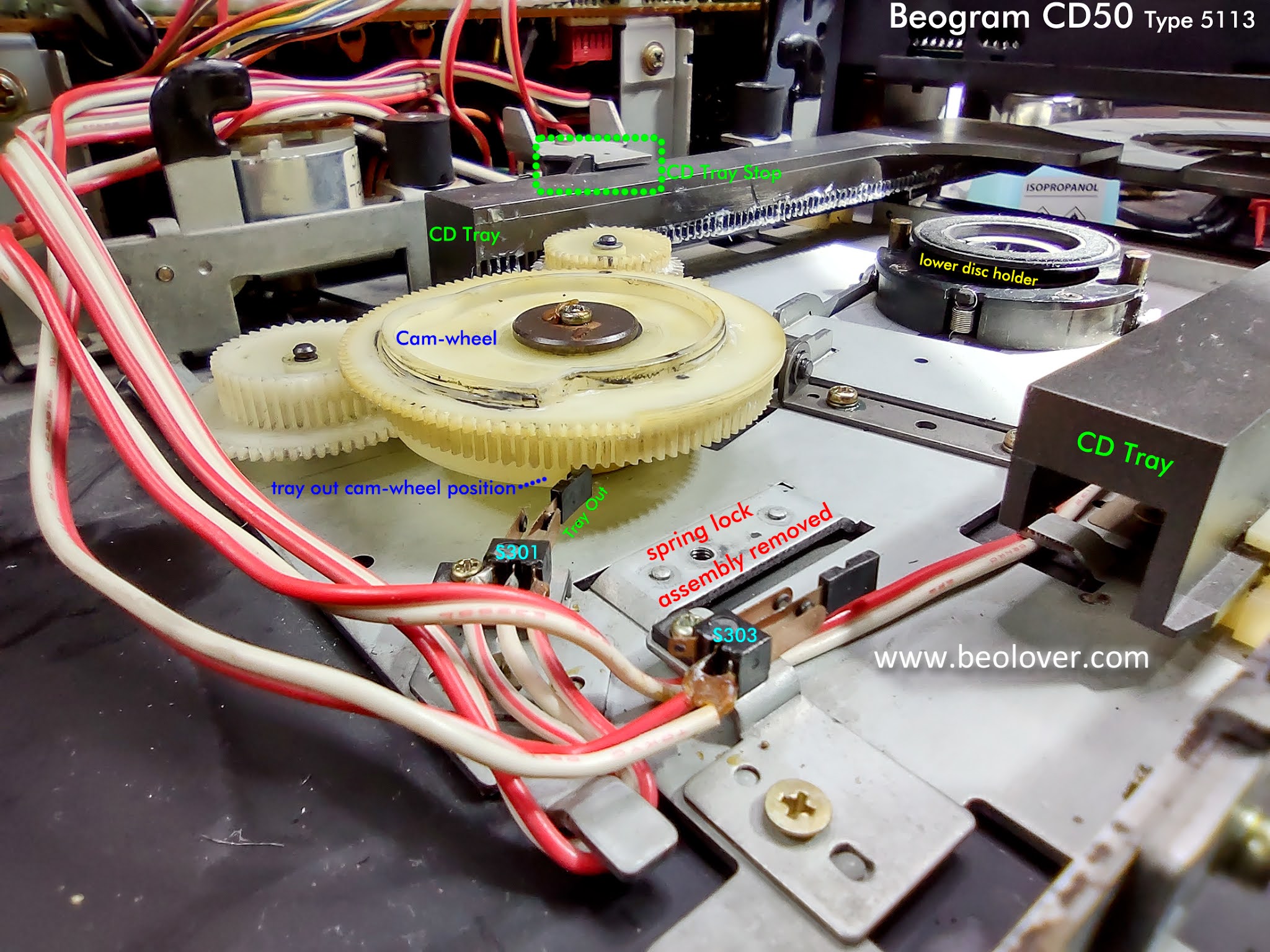


To get to the CD tray belt you have to remove the Cam-wheel.  That means removing the retaining nut from the Cam-wheel.


In the next photo I have removed the CD tray metal stop and taken the plastic CD tray out.  It is not necessary to remove the plastic tray but I occasionally do for more working room.  That is especially true if there is old rubber belt residue to clean up...as will be shown further down in this post.

When lifting off the Cam-wheel you will see that there are actually two Cam-wheel components.  The top Cam-wheel which rotates and causes the various CD loading steps to occur...and the lower (smaller) Cam-wheel component which operates the lifting and lowering of the lower disc holder.


NOTE: When removing the gear components to get to the belt replacement it is common practice to use a marking pen to mark the position of the gear relationships. I initially did that but my feeling now is that is not necessary.  It is much better to learn what the proper position of the Cam-wheel components and CD tray switches should be in for the various CD tray positions.  Learning that allows me to reassemble the gears and Cam-wheel components without the need for other guide marks.

Here is the top Cam-wheel removed.


Next comes the Gear-wheel that works with the pulley.
If you reach this step and the rubber belt is like the one pictured below or simply broken then the replacement task is simply to remove the old belt and attach a new one.


However....if you discover the old belt has deteriorated like this photo (from a later model CD50)


....then you have a bunch of belt residue cleanup ahead of you.  That will probably require some more disassembly in order to get the CD tray motor out as its pulley will have the gooey belt residue as well.

The next few photos show before and after pictures of the belt residue cleanup.


In either case, with the extra cleanup step or not, the result should be a nice new belt installed.

Now begins the reassembly.
The notations on the photos are important.  Begin the reassembly with the CD tray at the full open stop.


It is important that the retaining screw/washer/nut on the top Cam-wheel is not tight against the Cam-wheel.
The job of the retaining screw/washer/nut is to keep the Cam-wheel from coming off.  The Cam-wheel must be able to easily be turned by the tray gears.

Here is the CD50 tray mechanism in the tray closed position but with the lower CD clamp mechanism in its lowered position.


Here is the CD50 tray mechanism advanced to the CD clamping position (the position it will be in when playing a CD).


The CD50 Laser Module assembly can now be returned to its position over the CD tray assembly and the restoration tasks can move over to the capacitors on the CD50 circuit boards.

Here is a photo of the CD50 with the main boards identified.


Two of the three capacitors that I replace are on PCB 1 (Display & Key Control Board).
However, the main AC from the CD50 power cord enters the CD50 on this board on route to the transformer.  That being the case there is a 10nF X2 safety capacitor (1C28) on PCB 1.  At over 35 years of age the 1C28 capacitor is due for replacement.

PCB 1 also has a 100uF, 25V electrolytic capacitor (1C1) that is for the +5V power on the display board. When checking all of the electrolytic capacitors on the three CD50 units I recently worked on, all three 1C1 capacitors measured around 45uF instead of their rated 100uF. Quite a ways out of tolerance.

The third capacitor I replace is on PCB 8 (Decoder, System Control Board).  The capacitor there is 8C352.  A 33uF, 25V electrolytic capacitor.  Only one of the three CD50 units had a failed 8C352 capacitor.  It measured 30nF rather than 33uF.  The bad capacitor also prevented the CD50 audio muting circuit from functioning.  That makes sense as the audio muting circuit is what 8C352 is a part of.

I checked with other CD50 restorers and it turns out 8C352 has caused problems for other owners too.
As a precautionary measure I went ahead and replaced 8C352 on all three CD50 units I worked on.

Here is a photo of the two capacitors on PCB 1.

Before:


After:


Here is the 8C352 33uF capacitor on PCB 8

Before:


After:


Naturally it is possible for serious CD failures such as the Laser Module but for a typical, well taken care of Beogram CD50 that is just a victim of old age, the tasks listed here will usually get the unit back in good working order.

Saturday, June 19, 2021

Beogram CD50 From North Carolina: New Cabinet Feet, Ready To Return Home

The new cabinet feet for the Beogram CD50 arrived this week.  Installing them and wrapping up the listening tests were the final tasks of this project.

I discovered a problem with the original cabinet feet crumbling and falling apart while I had the CD50 partially disassembled during the CD tray belt replacement.  It is common for these rubber feet to deteriorate at this point in their age. Here are the original cabinet feet removed.


Only one piece remained intact but it was soon to fall apart like the others.
Bang & Olufsen used the same type of cabinets on their Beosystem 5000, 5500, 6500 and 7000.
That time period was from 1983 (introduction of the 5000) to 1995 (final period for the 7000).
So eventually all of the components for those systems will likely need these same type of rubber feet replaced at some point. I guess that is why Beoparts carries them :-).

I ordered some sets of these feet from Beoparts as my own 5000 and 5500 system components could use new feet as well.


The new feet simply press into place. Removing the old deteriorated pieces is the hardest part of the replacement.


After the new feet were installed it was back to the listening room to resume the listening tests.


After about twenty CD plays I think this CD50 is ready to be shipped home.

Sunday, June 13, 2021

Beogram CD50 From North Carolina: Power Supply Checks and Beosystem 5000 Test

The Beogram CD50 project is ready to wrap up.
I am waiting on some new rubber cabinet feet from Beoparts and those are on the way.
In the meantime I finished the internal CD50 testing by measuring the power supply voltages (+15V, -15V, +5V and -5V).


I checked the inside of the CD50 to see if it happened to have the stand-alone IR receiver for the remote control Bang & Olufsen offered as an option.  It is rare to find one with the IR receiver but I have the remote control so I always check.

This CD50 was the typical case and does not have the stand-alone IR receiver.
All of the remote control functionality occurs via cable between the CD50 and a Beomaster 5000.


...inside the CD50, an empty area where the optional IR receiver goes.


My final bit of testing then is to connect the CD50 to a Beomaster 5000 and operate it through the Beosystem 5000 remote control unit.


Everything is working correctly with this CD50.
I will continue some additional listening tests (as that is the best part about these restorations) until the new cabinet feet from Beoparts arrive.
After that this unit will be ready to ship home.

Wednesday, June 9, 2021

Beogram CD50 From North Carolina: Checking capacitors and re-assembly

 I left off the Beogram CD50 project having disassembled the unit to clean off old belt residue and replace the belt (for the CD tray mechanism).

While I had the CD50 disassembled I took a little time to examine the internal electronics and decide if I needed to replace any electrolytic capacitors. The usual case for vintage amplifier and turntable restorations is to replace all of the old electrolytic capacitors due to many (or most, in a lot of cases) being well out of tolerance at this point of their life.  The CD50 is now getting on thirty years old so the capacitors were a concern to me.

In checking with other CD50 restorers I found out that the electrolytic capacitors in the CD50 are usually still good so a complete replacement is not necessary.  Having never checked or replaced the capacitors in a Beogram CD50 I decided I would investigate myself. 

My plan was to go through and pull capacitors, measure them and replace them if necessary.

The capacitors I examined are the ones on the three main circuit boards.
PCB 1 (Display and Key Control), PCB 7 (Servo) and PCB 8 (Decoder & Power Supply).
I am not going to disassemble the front assembly of the CD50 for any of the display boards there. 

Here is a look at the three boards that have the capacitors I am going to look at.
This is how the components were oriented when the CD50 cabinet was first opened up.


The work on the CD tray mechanism required quite a bit of disassembly to where I now have full access to the circuit boards I want to examine the capacitors on.


Starting with PCB 1...
Note: I removed the metal shield box from the processor IC to reveal the two electrolytic capacitors underneath.


Starting with the the 1C1 100uF, 25V electrolytic capacitor I guess it was just good luck to try one that is out of tolerance right off the bat.


Definitely one to replace.
Right below it is the 1C28 safety capacitor. It isn't an electrolytic type capacitor but these capacitors are known to bust open when they fail and there are a few small crack lines in the device. It is better to go ahead and replace these now rather than wait for them to explode :-).


Here are the replacement capacitors installed.


The other three electrolytic capacitors on this board were two 10uF, 16V capacitors and another 100uF capacitor.
The 100uF was still in tolerance but close to the lower limit so I replaced it.
The two 10uF capacitors measured good but I decided to go ahead and replace them since I had already replaced the other capacitors on this board.


That was all for PCB 1.

Next up was PCB 8.


PCB 8 and PCB 7 have a lot of electrolytic capacitors.  I was prepared to replace all of them but it turned out that they were all still in spec. I did end up replacing all of the 100uF capacitors on PCB 8 like I did on PCB 1. The existing ones were in tolerance but a couple were far enough from the center value that I felt my new capacitors would be better to put in. Also, that way I know for certain those won't be a problem in the future. I also changed the 1000uF and 3300uF capacitors.  They also could have been left in place but I liked my replacement measurements better.

The rest of the capacitors on PCB 8 measured pretty much right on the specified value so I left them in.


The last board I checked was PCB 7.
That board turned out to just be a capacitor value check only. All of the electrolytic capacitors measured really good.


The next step is reassembly.
I took a lot of photos of the boards and their cabling when I was disassembling the CD50. That is something you should always do even if you know where all the parts go. You never know when you will want to go back and check exactly how things were connected before you started.

Here are the PCB 1, PCB 7 and PCB 8 boards connected back up.


I plugged the CD50 in and the CD tray mechanism now works.
After that I loaded a CD and connected the CD50 DIN cable up to the workshop Beomaster 8000 that I keep open (and fully functional) on my workbench.


I let the CD50 play the entire CD.  It properly returned to standby mode after it was done.
It's always a great feeling to see a component perform correctly after a big reassembly task.

The next step is to check some voltages in the CD50 before moving it to a listening room and connecting it up to my Beomaster 5000.  Then I can make sure all of the remote control functionality works properly.