In this post I will show the service manual adjustments I had to make for this Beogram 8002 restoration and go over the power supply voltage measurements. Once those are done I can check out the initial record play on the turntable. I will also take a look at the signals from the record detection circuit, the position sensor and the platter speed sensor to make sure they look healthy.
To be able to start playing a record I need to check a couple of things with the tangential arm assembly.
I have to make sure the distance from the platter surface to the top of the tonearm is 19.5 mm (per the service manual).
This is done by setting the fixed arm height to the required 19.5 mm value, then adjusting the tonearm to be horizontally parallel with the fixed arm.
In order to maneuver the arm assembly over the platter for this measurement and later, adjust the tracking force and tracking, I need to be able to move the arm but have the platter not spin.
That can be accomplished by unplugging the Beogram 8002, then unplugging the PCB 1 P4 connector.
Plugging the Beogram 8002 back into the AC outlet now permits operation of the Beogram without a moving platter.

Checking to see where the fixed arm height was to begin with I discovered it was low.
There is a screw at the rear of the fixed arm that is used to adjust the height for this service manual adjustment.
Using the fixed arm height adjustment screw I was able to set the required 19.5 mm distance with the platter.
That set the fixed arm height to be correct but of course the tonearm height must also be set at the same height. You can see that they are no longer aligned horizontally.
The tonearm height adjustment unfortunately means I must take the tangential arm assembly off the spindle and rails once again because the adjustment screw is underneath.
Now the arms are horizontally parallel again and 19.5 mm from the platter surface.
The next service manual adjustment to make is calibrating the tonearm tracking force.
In the photo above you can see that I left the slider control for the tracking force set to 1 gram.
For the adjustment I will attach a phono cartridge and see what the actual force is. If it needs adjustment I will move the tonearm counterweight so I measure 1 gram.
Here is the final tracking force measurement after a few adjustment iterations with the counterweight.
One more service manual adjustment now until I can play a record.
The tracking sensor that detects tonearm movement as a record is being played needs to be calibrated per the service manual so its sensitivity is correct.
There is a single adjustment screw on the side of the tracking sensor assembly for making the adjustment.


The adjustment is performed by setting the tonearm and phono cartridge down onto a test record.
Again...the platter must not be turning.
The service manual specifies using a Bang & Olufsen test record that I have never been able to find.
In its place I have a couple of records that I use for the adjustment and do so by checking the tracking sensor sensitivity on several different tracks.
The procedure says to lower the arm, then manually rotate the record while observing the servo motor that moves the arm. When properly adjusted the servo motor should begin moving the arm after 1 to 3 revolutions the first time (after the arm is lowered)...then every platter revolution after that.
Once the tracking sensitivity is set the Beogram is unplugged so the P4 connector can be plugged back in to PCB1. That will allow the platter to move again.
Here is the Beogram 8002 playing its first record since the restoration work was done.

I observed that the tonearm tracked correctly and that the arm assembly returned to the standby position automatically after record play.
It appears that the Beogram 8002 is functioning properly again. The restoration tasks all look correct.
To really check the electronic functionality though it is a good idea to measure the power supply components for +15, -15 and +5 VDC. I also like to view the sensor signals on an oscilloscope. That is just a good confirmation that the signals look like they are expected to.
Here are the power supply measurements.
+15 VDC : The filter capacitor C27 and the regulated value at P2-9.
-15 VDC : The filter capacitor C29 and the D26 anode.
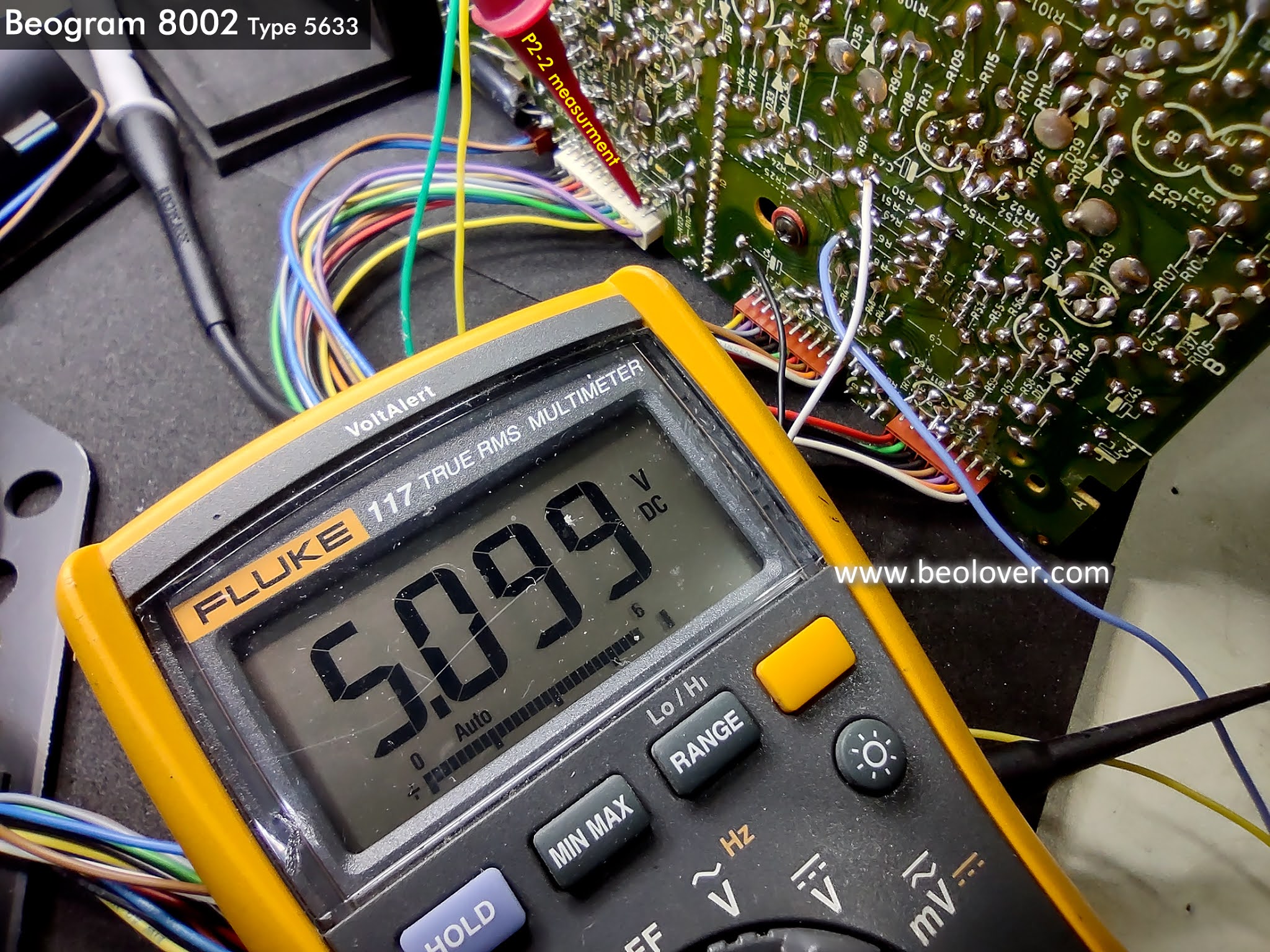
+5 VDC : The filter capacitor C24 and the regulated value at P2-2.
Everything looks as expected with the power supply voltages.
In using the Beogram I could see that the forward and reverse scanning controls work well but I hadn't actually measured and set them.
To do that I use my little test connector that I installed earlier. It has the ground, the forward LDR signal and the reverse LDR signal. Both signals should be set so they measure between 620mV and 700mV when the Beogram 8002 is in Play mode and not scanning.
Here is one of the initial measurements.
I like to set the value around 650mVolts.
It is hard to be really precise on the setting because the adjustment screws only provide a very coarse adjustment.
I will wrap up the checks on the oscilloscope.
Here are the measurement locations again for the oscilloscope probes.
I connected to the arm detection sensor, the two arm position sensors and the platter speed sensor.
As a starting reference point here are sensor signals when the Beogram 8002 is in Standby mode.
Pressing the Play button with an empty platter will cause the Beogram 8002 to start rotating the platter, lock in the speed at 33.33 RPM and scan for a record to play. At around the 17cm mark the platter speed will switch to 45 RPM. Shortly after that, if no record is found the Beogram will stop and return the tonearm back to its standby position.
Here are the oscilloscope events for that.
In the above photos you can see how the arm detector and speed sensor signals vary at 33.33 RPM and 45 RPM.
Here are the signals again but with a record on the platter and as the Beogram plays the record.
The arm detector signal does its usual start up pulse but then settles at 0V because the record is on the platter covering up the reflective patterns.
Also notice that the position sensors are pretty constant as the tonearm is scanning.
Once the tonearm is lowered to play the record the platter speed is constant, the arm detector is at 0V and the two position sensors are at varying values due to the servo position control making incremental movements to play the record.
I think this Beogram is ready to reinstall in its cabinet and move to some record play listening tests for a while.