After a short break from the workbench I am ready to wrap up this Beogram 8002 project.
I left off with all of the Beogram 8002 functions tested out successfully.
In this post I will re-install the Beogram floating chassis back into the cabinet and reattach the dustcover and metal lid.
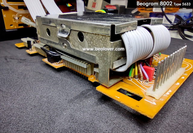
First however, I need to remove the test leads I installed for the oscilloscope measurements and I need to close the microcomputer metal box.
The lid for the microcomputer shield box contains a heatsink bar that requires some fresh thermal grease before closing it back up.
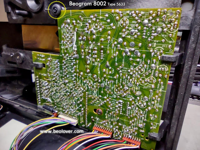
Next is the power supply transformer box. It slides into place from the top and the connector mates with PCB 1.
The Beogram cabinet can now be closed from its service position and the floating chassis suspended from its three hangers.
So far so good.
Now is a good time to recheck the Beogram 8002 operation. It is easy to open the Beogram back up for any fix if needed at this point.
I get the Standby light when the Beogram 8002 is plugged in.
That demonstrates to me that everything internally is still good.
Now I can move forward with the install of the dust cover and metal lid.
This photo shows the damped hinge mount for the metal lid.
This photo shows the right end of the cabinet back...where the phono cable connection is.
I test fit the dust cover spring mechanism while it is easy to get to everything for adjustment.
The fit was perfect so I was able to continue on and mount the dust cover assembly.
I adjusted the tension on the leaf spring for the dust cover assembly so it would hold position when the dust cover was partially closed (or open).
Here is the dust cover closed.
I believe this Beogram is ready for some test play of record albums.
While I am doing that I will fashion some bumper pads for the metal lid and the front part of the dust cover as the original bumpers are long deteriorated.
Next time I should have the bumper pads installed and will be listening to records on this Beogram.


No comments:
Post a Comment
Comments and suggestions are welcome!