Featured Post

Beolover SyncDrive: DC Platter Motor Replacement for Beogram 4002 and 4004 (Type 551x and 552x)

Late Beogram 4002 and the 4004 (Types 551x and 552x), which have DC platter motors instead of the earlier synchronous AC motors usually suff...

Showing posts with label keyboard. Show all posts

Monday, November 23, 2015

Beogram 4000: Installation of New Reservoir and Motor Phase Capacitors Using a 3D Printed Adapter

It was time to replace the big capacitors in the Beogram 4000 that I am rebuilding right now. I always enjoy this procedure, especially due to the clean install enabled by my 3D printed adapter. It accommodates smaller modern capacitor units, while giving the entire set-up an organized look. I made an earlier post that shows in detail what leads are connected where, in case you get confused while doing this procedure...there are a quite a few jumpers to re-solder...;-).

Here is a picture of my capacitor kit with adapter (this is available to other enthusiasts - just send me an email). The two back-to-back caps on the left replace the original bipolar AC motor phase capacitor. The adapter has notches that fit to the original capacitor mounting strap holding everything firmly in place:

I used this kit to replace this fairly messy original set-up:

This is how it looks now after installation:

And here a detail picture of the connections:

On to recapping the PCBs and adjusting the motor trimmers.


Saturday, November 21, 2015

Beogram 4000: Cleaning the Switches

One of the main trouble areas of the Beogram 4000 design are the many mechanical unencapsulated switches throughout the units. In my experience, most usability issues have their root-cause in one or more switches that are oxidized or have bent contact tabs. Often, when issues arise people try to fix them by bending the contact tabs and that usually results in even worse performance. The Beogram that I am restoring right now was no exception. When I tested its functions after replacing the alien solenoid I found that the slide transfer button to the right did not work.
So when I replaced the light bulbs in the control panel with SMD LEDs I also cleaned the contacts of the switches. The make-switches (DOWN/ON/OFF/33/45) can be restored by simply sliding some 2000 grit sand paper through the contact areas while pressing the switches and then adding some DeoxIT D-100 to the area. However the slide transfer buttons to the left ("<") and the right (">") are both break- (slow scanning) and make-(fast scanning) switches, while the UP-button is a break switch. Since break switches make their contact solely via the spring forces of the switches they need to be cleaned more thoroughly. It turns out that these switches are best extracted and then cleaned with a fiber glass pen followed by a thin DeoxIT coat. After that treatment they usually start working again.
This shows the left scanning switch taken out. It was very oxidized

This shows it after cleaning it with a fiber glass pen and re-installing it:

Her is the right one:

And after installation:

And finally the UP switch before

and after cleaning:

After this was done the scanning function was restored. Then I did the position switches that trigger needle drop at the standard vinyl diameters and also govern start and stop behavior. These switches are below the carriage assembly, i.e. one needs to take out the position indicator (careful with this since it is easy to break off the red indicator - this Beogram already suffered this indignity at some point as is indicated by the glued indicator). This shows the switches as I found them. They were covered with a lot of grey grease:

I cleaned everything,

and then I removed the two screws that hold the PCB in place after which I was able to lift it up:

The 2000 grit treatment followed by some DeoxIT D-100 did the trick. Now the control system works again smoothly.


Monday, June 1, 2015

Beogram 4002: Awesome Refurbished Keypads in the House!

Today, I received a small package from Denmark containing two refurbished Beogram 4002 keypads.  As my beofriend put it 'the weather was right' for the paint job, and it appears he was right! Here is a picture of these beauties:


He is an absolute artist! They really look like they just rolled off the B&O line in 1975! Wonderful job! I sent him the worn out keypad of a recent Beogram 4002 restoration that I did, and then he found an additional one! I just wanted to have them available for my next 4002 restorations. I'll be happy to get you in touch with my friend if you would like to send him your keypad. Don't try this at home! This needs the "Master's Touch"!...;-)


Thursday, December 18, 2014

Beogram 4002/4004: Rebuilt Keypad Surface

A good day in beolover's life! I received a rebuilt Beogram 4002 keypad from a fellow 'beofriend' in Denmark. He is able to refinish the keypad surfaces to the original splendor. I was absolutely amazed when I received the package. The resurfaced switches looked 99% like the original. Very awesome! This will give the 4002 that I am restoring a pristine look. Well worth the money!

Here are a couple pictures. The first one shows the old pad with the circuit board removed for exchange to the rebuilt one. The usual damage to the keys from pressing on the surfaces with bare fingers is clearly apparent. Skin acids in combination with mechanical abrasion eats the surface finish over time, and a smudged appearance occurs. If you look closely, on the start key the finish is fully gone in a few spots. Absolutely un-beolovely!


Below is the rebuilt keypad. Absolutely pristine looking. If you hold it next to the damaged one, the pads have very much the same appearance. I am stunned! Like I time machined back to 1975 and picked one up at the B&O store! Excellent job! 


Saturday, September 20, 2014

Beomaster 8000: Intermittent Display Digits - Bad Solder Joints

Oh well...While I was cheerfully listening to an episode of Car Talk on NPR on the Beomaster 8000 that will soon go to Australia, I could not help noticing a couple digits in the freshly restored frequency display fluctuating -on-off-on-off...Back to the bench with this one! It really is a nice workout, carrying the 45 pound behemoth to my electronics lab...;-).

The digits that blinked suggested a problem with the Phase 3 strobe that governs two digits in the frequency display, as well as the balance digit. I quickly found the problem: A broken solder joint at P74 that, among other signals, connects Phase 3 to pin 15 of 9IC3 (the master microprocessor). Here is a picture of the solder joints of the connector:


If you look carefully, you will notice the shadow around the leftmost joint...this indicates a broken out joint.

I re-soldered all jacks and plugs on the two joined PCBs and now all is fine. These two large, but poorly mechanically supported boards are really the most problematic area of the 8000s...whenever there is erratic behavior, it is usually some solder joints or vias on #8 or #9. I will add the re-soldering of the board-to-board connectors to my standard Beomaster 8000 restoration process. Live and learn!

Back to the living room for some more in the field testing before the long journey.

Saturday, September 6, 2014

Beomaster 8000: Display Restoration with SMD LEDs - Reassembling the Display Units

The SMD LEDs that I put into the Beomaster 8000 displays survived the 48 hrs test without problems. Time to put the display units back together. I applied the method I outlined earlier in this blog:

http://beolover.blogspot.com/2012/09/beomaster-8000-display-repair-hopefully.html

After I glued the transparency foil pieces to the back of the displays, I fixed them with carpenter clamps:


And after extracting them from the clamps:


Then I replaced R14 and R16 with 3.3kOhm and 1.5kOhm resistors to adjust the display voltage to reduce the intensity of the LEDs. See this blog entry for details about the adjustment procedure:

http://beolover.blogspot.com/2012/05/beomaster-8000-display-brightness.html

Then it was time to solder the displays back in. The insertion of the displays back into the board is tricky since one needs to line up all the pins at once...patience and calm music pays here...;-). Here is the display board after installation:


I adjusted trimmer R15 to get about 3.1V keyboard strobe (yellow) and about 4V on the LED rail (blue). It is important that the keyboard strobe does not go below 2.7V (see above blog entry for a discussion):


Looks like we are almost done. The last step before I put it back together is to check on the processor board.

Sunday, September 23, 2012

Beomaster 8000 Keyboard Restoration/Not Working Buttons

The final step to restore my Beomaster 8000 to its original glory was to fix a keyboard issue. I noticed earlier that the TP2 button only worked intermittently. I thought that this was a problem originating from corroded keyboard contacts since wiggling the button seemed to do the trick once in a while.... Hence, I took the keyboard apart to clean the contacts. While this was an interesting exercise, it turned out that this did not fix the problem. But more about that below. First a few pictures of the keyboard innards:

Removing the retaining washers turned out to be a pain. Since B&O used one-time use washers that need to be destroyed for removal I had to cut them off with a wire cutter:


This photo shows the buttons from below after removing the PCB and a plastic foil:

Here a shot of the PCB before cleaning:


For cleaning the contact pads have to be removed:

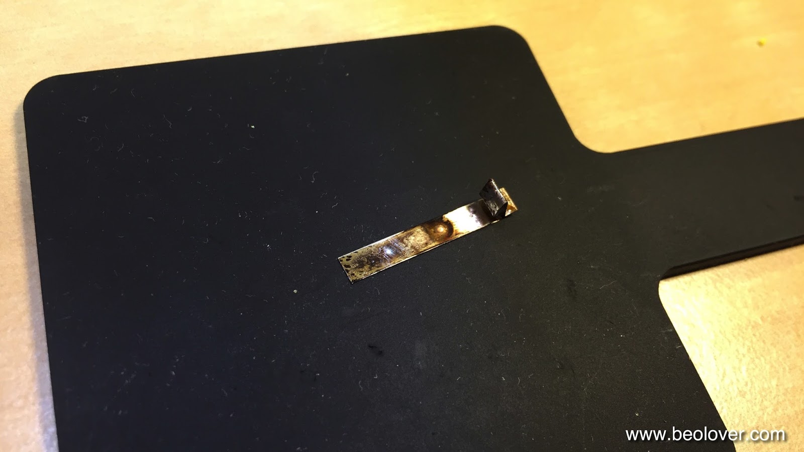
These contacts were quite oxidized (or probably rather sulfidized, assuming that the pads are silver coated)

Using a small head Eurotool fiber brush (I am grateful to Gunther at Beoworld.org for this excellent tip!!) I cleaned the contacts:

The above picture shows the PCB after reassembly.

I reinstalled the board using 3 mm external retaining rings from Grainger (113828) and #4 nylon washers. This is shown here:


So far so good. Plugging the keyboard back into the Beomaster and turning it on immediately revealed that this procedure did not fix the problem.

After playing a bit around I realized that the P4 button also not worked whenever TP2 was out. A look at the circuit diagram for the processor board immediately revealed that TP2 and P4 use the same input on the slave processor (it distinguishes between the two buttons via the strobe mechanism that also drives the LEDs of the display in three "phases"). The oscilloscope showed that after pressing the TP2 or P4 buttons the voltage at P81-7 (7th pin on plug 81 that goes to the microcontroller) was higher than on other pins connected to working buttons. This led to the conclusion that the connection between switch and microcontroller must be interrupted whenever the buttons ceased operation.

Hooking up an Ohmmeter between pin 7 and R103 indeed revealed a broken PCB trace, with an intermittent contact depending on the flex of the PCB in the vicinity of P81. I installed a bypass (pink wire in picture):

This seems to have done the trick. TP2 and P4 seem now stable.

After this I finally put the Beomaster back together. Tomorrow, I will swap it with the one I currently use in the living room and the next months will show if this rebuild is stable. At this point all features seem to work correctly. On to the next B&O!