One of the main trouble areas of the Beogram 4000 design are the many mechanical unencapsulated switches throughout the units. In my experience, most usability issues have their root-cause in one or more switches that are oxidized or have bent contact tabs. Often, when issues arise people try to fix them by bending the contact tabs and that usually results in even worse performance. The Beogram that I am restoring right now was no exception. When I tested its functions after replacing the alien solenoid I found that the slide transfer button to the right did not work.
So when I replaced the light bulbs in the control panel with SMD LEDs I also cleaned the contacts of the switches. The make-switches (DOWN/ON/OFF/33/45) can be restored by simply sliding some 2000 grit sand paper through the contact areas while pressing the switches and then adding some DeoxIT D-100 to the area. However the slide transfer buttons to the left ("<") and the right (">") are both break- (slow scanning) and make-(fast scanning) switches, while the UP-button is a break switch. Since break switches make their contact solely via the spring forces of the switches they need to be cleaned more thoroughly. It turns out that these switches are best extracted and then cleaned with a fiber glass pen followed by a thin DeoxIT coat. After that treatment they usually start working again.
This shows the left scanning switch taken out. It was very oxidized

This shows it after cleaning it with a fiber glass pen and re-installing it:

Her is the right one:

And after installation:

And finally the UP switch before
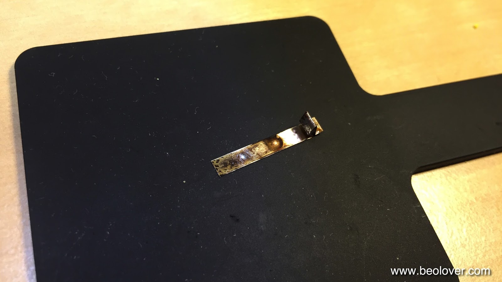
and after cleaning:

After this was done the scanning function was restored. Then I did the position switches that trigger needle drop at the standard vinyl diameters and also govern start and stop behavior. These switches are below the carriage assembly, i.e. one needs to take out the position indicator (careful with this since it is easy to break off the red indicator - this Beogram already suffered this indignity at some point as is indicated by the glued indicator). This shows the switches as I found them. They were covered with a lot of grey grease:

I cleaned everything,

and then I removed the two screws that hold the PCB in place after which I was able to lift it up:

The 2000 grit treatment followed by some DeoxIT D-100 did the trick. Now the control system works again smoothly.
No comments:
Post a Comment
Comments and suggestions are welcome!