Featured Post

Beolover SyncDrive: DC Platter Motor Replacement for Beogram 4002 and 4004 (Type 551x and 552x)

Late Beogram 4002 and the 4004 (Types 551x and 552x), which have DC platter motors instead of the earlier synchronous AC motors usually suff...

Showing posts with label missing. Show all posts

Sunday, December 18, 2016

Beogram 8002: Repair of a Dead Display Digit

Another issue plaguing the Beogram 8002 that I am finishing up right now was that the fourth digit of the RPM display was dead. This shows the sorry state of affairs before my repair:

Since all segments of this digit were not working the most likely root cause of the issue was a missing strobe signal for this digit. A measurement with my oscilloscope at the strobe pin (14) on the display confirmed this hypothesis. Time to 'follow the signal', which is not the most straight forward thing to do in this setup since the unit must be running to do the measurements. I installed some micro-grabber leads in the microcontroller can at strategically important points and then did the measurements with the board installed. It turned out that the trace that connects processor pin 13 to the base of IC6 (the Darlington that drives digit 4) was interrupted midway (between the solder points of the white and ground leads):
The way this looked suggested that this was probably the result of 'human interaction', and of course one wonders what may have compelled anyone to poke around there with a sharp object causing the trace to come off. Anyway, I reestablished contact with a piece of magnet wire:
and the display digit came to life again:
Time to put the hood back on, do the mechanical adjustments and then do some 'reliability testing' (= listening to some awesome vinyls I recently bought...;-) on this lovely Beogram 8002.


Thursday, November 17, 2016

Beomaster 8000: Repair of a Damaged In DIN7 Phono Jack That Had Lost All Four Panel Mount Tabs

One of the weak spots in Beomaster 8000s are the phono jacks in the input box under the control panel. The plastic of these jacks becomes brittle over the years, and all it takes to break out the plastic tabs that hold the jack above the input box panel is a firm push to get the DIN7 plug from a Beogram into the jack. And then the jack is inside the connector box, and the cable probably not even connected. And this is how this sorry outcome looks like:
Usually, only the top (outside) tabs break off, and there is a fix for this with two 3D printed inserts that replace these tabs. A detailed report on this repair and a video is posted here. This shows the tabs that I installed in this Beomaster:
These tab replacements are available to other enthusiasts via the Beolover Shapeways store. By the way, they also repair the jack on Beocord 8000 and 9000 units. They are also often broken out.

Unfortunately, this Beomaster's DIN7 jack posed a new challenge: It's inside tabs that hold it below the panel (so one can pull the plug without dislodging the jack) were also gone.

Since the original jacks are impossible to find these days, and even replacements from donor units are very hard to come by, I had no other recourse than trying fixing this with yet more 3D printed parts!

But first I needed to repair several disconnected leads, which probably were a casualty of a previous repair attempt. Several jumpers were broken off:
Luckily, while repairing the contact box of another Beomaster 8000 I made an extensive sketch of all the wire connections in this box, and so I was able to restore the connections without trouble:
After this I designed the replacement tab for the right side of the jack. Since it is pretty much impossible to print flexible precision parts on this size scale, I resorted to a two-pronged approach, where I first designed a static tab without spring force that would be glued onto one of the sides of the jack. This would allow to insert the jack diagonally into the cutout together with the outside tab replacements. Then, once seated, the plan was to glue another static tab into the other side of the jack from the inside of the box.

Alright, that was the plan...and here is the execution:

This shows the right side tab:
It fits into the side 'cavity' of the jack that is shown here:
This shows the part seated (with a dab of epoxy underneath):
I clamped it for an hour until I could be sure that the epoxy was fully hardened:
Then I inserted the jack together with the top tabs:
The next step was to design a tab for the other (left) side of the jack that I could get into the 'cavity' from the inside of the connector box:
I made it considerably longer than the other one. This gave me enough 'meat' to handle it on the inside and guide it into the space between jack and panel. I put some double sided tape on the contact surface and then inserted it into the space:
The part fits very snugly, and my hope is that the double sided tape will hold it in place reliably once pressed in. This will allow extracting the jack again if necessary in the future, in case there are further repairs necessary etc...I always thrive to make my repairs and updates 'reversible' in case a better solution comes along in the future.

The tight fit required me to use tongue and groove pliers adjusted to fit the task:
And this is how it looked after the repair was completed:
Almost like new! Beolovely! I gave this assembly a bunch of plug-in and -outs with a tight fitting DIN7 cable, and it seems to hold up nicely. But I will recommend to my customer to hold the jack down while pulling out the plug. Looks like we are getting close to buttoning this baby up and giving her a first spin!


Thursday, November 10, 2016

Beomaster 8000: Step Five (2) - Rebuilding the Displays and Indicator Lights with SMD LEDs


After 24 hours the LEDs were all still in business, and so I decided to put the displays back together. My current method is to press the display covers onto the PCBs with carpenter clamps and then use black hot glue to seal the sides of the display units. This keeps them together reliably, while it is still reversible - with some effort the glue can be peeled off to open them again. I like solutions like this since no one (and no electronic component) is 100% perfect, and so it is nice if one can repair things (again) at a later date if necessary.

After putting the displays back together I usually run them for another 24 hours to make sure that the assembly process did not inflict damages on the SMD LEDs:
While this test was running, I did the rest of the display PCB. I replaced the two electrolytic capacitors with 105C grade Japanese units and then I went on to replace the four incandescent light bulbs that illuminate the indicators (clipping, filters, mono, and manual tuning). This shows the right two bulbs in their reflector boxes:
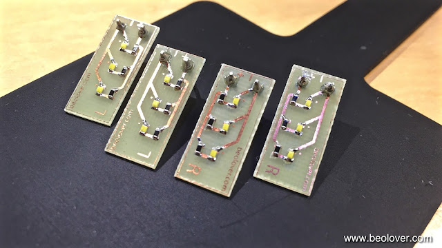
The original bulbs usually have very weak leads since they corrode over time. The slightest motion of the bulbs can break them off. Therefore, I developed a SMD LED based solution to replace them. This shows them in place of the bulbs with the reflector box removed:
There need to be two versions of these SMD LED boards since the reflector cases are mirrored for the left side, i.e. the polarity is reversed (which plays a role for LEDs while bulbs are impervious to the current direction): 
And here with the reflectors put in place:
After the 24 hrs test I soldered the displays back into the PCB:
Before I test this board in situ I will restore the microcontroller board...more about this in the next post of this project.


Tuesday, November 8, 2016

Beomaster 8000: Step Five - Rebuilding the Displays and Indicator Lights with SMD LEDs

No Beomaster 8000 restoration is complete without rebuilding the displays. They will all fail eventually, and most in the near future. And since those beautiful large LED displays are a main design feature of this lovely receiver, nothing is more frustrating than having a few missing segments. No matter how good the condition of the enclosure, when the displays are not complete it just looks sad! Not beolovely at all!

Luckily the displays are large enough that one can update them with 0603 packaged SMD LEDs, which can still soldered fairly well by hand. For this to happen one needs to extract the displays from the display board:
Once liberated, the next step is to open them up and scrape off the original LEDs, which are directly bonded to the PCB...truly a 1980s design!:
Once the pads are prepared it is time to line up the SMD LEDs and solder them into the places of the original LEDs:
The critical element here is to place the SMD LEDs precisely into the areas that are underneath the light guides in the LED assemblies (white parts with long slots in the picture above) when assembled. If they are not centered, the LEDs will get damaged during re-assembling the displays since the light guides will exert lateral pressure on the LED packages, which can result in them breaking off their pads. I do this by soldering the LEDs on only one side, then checking where the LEDs come close to the light guide slot walls, and then I correct the position of those that are a bit off. Once all are properly in place, I solder them on the other side.
After soldering all the LEDs in, it was time to give the boards their first 24 hrs test. For this I have a breadboard setup that mimics the wiring on the display PCB:
Let's see if they are still all on tomorrow!


Tuesday, August 2, 2016

Beomaster 8000 Terminal: Replacement of Corroded Battery Terminals and the Design of a New 3D Printed Battery Cover

The Beomaster 6000 that I just repaired came with a non-working Beomaster 8000 Terminal remote control. It turned out that a simple replacement of the corroded battery terminals was enough to restore power and with that the functionality of the unit. However, this Terminal was also lacking the battery cover and the rubber bumpers that keep it from sliding off polished furniture surfaces. Since this is not the first Terminal that I saw with lacking battery compartment cover, I decided to design a 3D printed replacement part. Here are a few impressions of my progress:

This shows the original corroded battery terminals:
and the installed replacement:

After a few design iterations I had a fitting battery compartment cover:
This shows it in comparison with the cover I extracted from one of my Terminals. Here the outside surface of the part:
The part has rubber bumpers like the original. Thir location is slightly different due to stability considerations, but they do their job very well.
This shows the part installed:

Pretty, eh?? The latch works exactly like in the original part. The cover can be extracted from the ouside by inserting a small flat blade screw driver and then lifting it out.

But why in orange you may wonder?!? I usually use orange for prototyping since I have an ample supply on hand these days for filling CleanerVinyl orders. Orange also reveals more details than black in photographs. But of course the final version was printed in black. Here in comparison with the original:
And in more detail:
If you are lacking the battery compartment cover on your Terminal, this part is available for purchase. Just send me message (use the contact form on the left).

The remaining task was to replace the worn/missing rubber bumpers at the lower end of the Terminal body. This shows a newly installed bumper (right) in comparison with a broken off original bumper (left):
And both replaced:
The final step was to clean the unit. I employed my ultrasonic cleaner (another benefit of the CleanerVinyl project...;-) and the buttons and housing came out in a fairly pristine condition:
What a lovely classic design! This is Beolove!


Wednesday, October 28, 2015

Beomaster 8000: Display Restoration with SMD LEDs

After I replaced the indicator light bulbs of the Beomaster 8000 that I am restoring right now I did the 7-segment displays. The 7-segment displays are essential for the signature looks of the 8000 and dead segments are at best annoying. I usually recommend to rebuild the displays even if they are still o.k. since the death of individual segments is virtually unavoidable considering the age of the units and the potential rigors of shipping. The original LEDs in these displays are not encapsulated, i.e. the bonded contact wires are not protected against vibration and thermal challenges etc.... Therefore, the usual failure mode is loss of contact at the bonding locations. Final failure is often preceded by intermittence as these wire bonds. This Beomaster had a few segments in this stage, which may or may not explain the claim by the seller that the displays were in good working condition. I posted many entries in the past about my restoration process, a summary can be found on my dedicated Beomaster 8000 page. The pictures shown here are posted to document the work done on this particular Beomaster 8000.

This shows the display board after I extracted it:

This shows the displays after unsoldering them. It is mandatory to use a desolder gun for removing them to prevent damage to the fragile pre-FR4 age PCB:

Then I liberated the displays from their plastic mounts,

and opened them up:
Then I removed the original LEDs and then soldered SMD LEDs into place. Then it was time for my 24hrs test where I power the boards from a test-jig that I set up with a couple solders breadboards:

Then I put the covers back on and tested them again to make sure all segments survived the procedure:

Then it was time to solder the displays back in. Here you can see them mounted back on their plastic mounts:

And back on the PCB: 
And fired up together with the newly rebuilt indicator lights (unfortunately I forgot to use a FM preset, so the source display is dark in this picture). The volume is a 6.0 to get the clipping indicator to light up:

On to the uProcessor board.


Beomaster 8000: Replacing the Incandescent Indicator Light Bulbs with SMD LEDs

I always enjoy rebuilding the display board of Beomaster 8000s. So much of the signature looks of these units depends on the gorgeous large 7-segment displays and the masked indicator lights for clipping, filters, mono and manual tuning. With this particular unit I started out by replacing the indicator bulbs with my recently designed SMD LED based replacement boards. There are two versions of this board accommodating the two left and right incandescent bulb cabinets. The contact pads for the bulbs are mirrored in these compartments, while the polarity remains the same. This mirror symmetry requires different boards to accommodate polar devices like LEDs. Here is a picture of the boards that I installed:

When I developed these boards I made a video how to install them:

It is important to keep in mind that the LED boards run on a much smaller current than the light bulbs, and this requires the removal of the resistors R34/36/38 and 40 on the display board. Otherwise the LEDs will always be on.

This shows the original light bulbs in their cabinets:

And after replacement with the SMD LED boards:

And in on condition:

On to rebuilding the 7-segment displays.