Featured Post

Beolover SyncDrive: DC Platter Motor Replacement for Beogram 4002 and 4004 (Type 551x and 552x)

Late Beogram 4002 and the 4004 (Types 551x and 552x), which have DC platter motors instead of the earlier synchronous AC motors usually suff...

Showing posts with label segment. Show all posts

Thursday, November 10, 2016

Beomaster 8000: Step Five (2) - Rebuilding the Displays and Indicator Lights with SMD LEDs


After 24 hours the LEDs were all still in business, and so I decided to put the displays back together. My current method is to press the display covers onto the PCBs with carpenter clamps and then use black hot glue to seal the sides of the display units. This keeps them together reliably, while it is still reversible - with some effort the glue can be peeled off to open them again. I like solutions like this since no one (and no electronic component) is 100% perfect, and so it is nice if one can repair things (again) at a later date if necessary.

After putting the displays back together I usually run them for another 24 hours to make sure that the assembly process did not inflict damages on the SMD LEDs:
While this test was running, I did the rest of the display PCB. I replaced the two electrolytic capacitors with 105C grade Japanese units and then I went on to replace the four incandescent light bulbs that illuminate the indicators (clipping, filters, mono, and manual tuning). This shows the right two bulbs in their reflector boxes:
The original bulbs usually have very weak leads since they corrode over time. The slightest motion of the bulbs can break them off. Therefore, I developed a SMD LED based solution to replace them. This shows them in place of the bulbs with the reflector box removed:
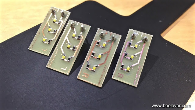
There need to be two versions of these SMD LED boards since the reflector cases are mirrored for the left side, i.e. the polarity is reversed (which plays a role for LEDs while bulbs are impervious to the current direction): 
And here with the reflectors put in place:
After the 24 hrs test I soldered the displays back into the PCB:
Before I test this board in situ I will restore the microcontroller board...more about this in the next post of this project.


Tuesday, November 8, 2016

Beomaster 8000: Step Five - Rebuilding the Displays and Indicator Lights with SMD LEDs

No Beomaster 8000 restoration is complete without rebuilding the displays. They will all fail eventually, and most in the near future. And since those beautiful large LED displays are a main design feature of this lovely receiver, nothing is more frustrating than having a few missing segments. No matter how good the condition of the enclosure, when the displays are not complete it just looks sad! Not beolovely at all!

Luckily the displays are large enough that one can update them with 0603 packaged SMD LEDs, which can still soldered fairly well by hand. For this to happen one needs to extract the displays from the display board:
Once liberated, the next step is to open them up and scrape off the original LEDs, which are directly bonded to the PCB...truly a 1980s design!:
Once the pads are prepared it is time to line up the SMD LEDs and solder them into the places of the original LEDs:
The critical element here is to place the SMD LEDs precisely into the areas that are underneath the light guides in the LED assemblies (white parts with long slots in the picture above) when assembled. If they are not centered, the LEDs will get damaged during re-assembling the displays since the light guides will exert lateral pressure on the LED packages, which can result in them breaking off their pads. I do this by soldering the LEDs on only one side, then checking where the LEDs come close to the light guide slot walls, and then I correct the position of those that are a bit off. Once all are properly in place, I solder them on the other side.
After soldering all the LEDs in, it was time to give the boards their first 24 hrs test. For this I have a breadboard setup that mimics the wiring on the display PCB:
Let's see if they are still all on tomorrow!


Wednesday, October 28, 2015

Beomaster 8000: Display Restoration with SMD LEDs

After I replaced the indicator light bulbs of the Beomaster 8000 that I am restoring right now I did the 7-segment displays. The 7-segment displays are essential for the signature looks of the 8000 and dead segments are at best annoying. I usually recommend to rebuild the displays even if they are still o.k. since the death of individual segments is virtually unavoidable considering the age of the units and the potential rigors of shipping. The original LEDs in these displays are not encapsulated, i.e. the bonded contact wires are not protected against vibration and thermal challenges etc.... Therefore, the usual failure mode is loss of contact at the bonding locations. Final failure is often preceded by intermittence as these wire bonds. This Beomaster had a few segments in this stage, which may or may not explain the claim by the seller that the displays were in good working condition. I posted many entries in the past about my restoration process, a summary can be found on my dedicated Beomaster 8000 page. The pictures shown here are posted to document the work done on this particular Beomaster 8000.

This shows the display board after I extracted it:

This shows the displays after unsoldering them. It is mandatory to use a desolder gun for removing them to prevent damage to the fragile pre-FR4 age PCB:

Then I liberated the displays from their plastic mounts,

and opened them up:
Then I removed the original LEDs and then soldered SMD LEDs into place. Then it was time for my 24hrs test where I power the boards from a test-jig that I set up with a couple solders breadboards:

Then I put the covers back on and tested them again to make sure all segments survived the procedure:

Then it was time to solder the displays back in. Here you can see them mounted back on their plastic mounts:

And back on the PCB: 
And fired up together with the newly rebuilt indicator lights (unfortunately I forgot to use a FM preset, so the source display is dark in this picture). The volume is a 6.0 to get the clipping indicator to light up:

On to the uProcessor board.


Beomaster 8000: Replacing the Incandescent Indicator Light Bulbs with SMD LEDs

I always enjoy rebuilding the display board of Beomaster 8000s. So much of the signature looks of these units depends on the gorgeous large 7-segment displays and the masked indicator lights for clipping, filters, mono and manual tuning. With this particular unit I started out by replacing the indicator bulbs with my recently designed SMD LED based replacement boards. There are two versions of this board accommodating the two left and right incandescent bulb cabinets. The contact pads for the bulbs are mirrored in these compartments, while the polarity remains the same. This mirror symmetry requires different boards to accommodate polar devices like LEDs. Here is a picture of the boards that I installed:

When I developed these boards I made a video how to install them:

It is important to keep in mind that the LED boards run on a much smaller current than the light bulbs, and this requires the removal of the resistors R34/36/38 and 40 on the display board. Otherwise the LEDs will always be on.

This shows the original light bulbs in their cabinets:

And after replacement with the SMD LED boards:

And in on condition:

On to rebuilding the 7-segment displays.


Saturday, May 30, 2015

Beocord 9000: Display Restoration with SMD LEDs

Like most Beocord 9000 and Beomaster 8000 units the Beocord 9000 that I am rebuilding right now has a broken 7-segment display. In this case, only one segment was missing, but of course this needed to be fixed, these big early LED displays are one of the stunning aspects of these units. I can understand that Jacob Jensen was fond of using them:

This display is very similar to the frequency display of a Beomaster 8000. However the design is somewhat different, so they are not interchangeable. The restoration process however is the same. I made many posts in the past about it, see here for example.

Taking the display out is slightly different due to the bezel that is clamped to PCB #1 that holds them in place and also prevents any light from the back and sides of the display to escape. This is superior to the earlier design of the Beomaster 8000. The first step is to remove PCB#11 and then the bezel. Then the display can be unsoldered. A desolder gun is essential for this task since all pins need to be able to move freely when it is taken out:

After opening the display unit up, the first task was to determine the correct current limiting resistors for the SMD LEDs (Newark 75K1441). The Beocord 9000 circuit has no easy way like the Beomaster 8000 for tuning the display intensity, so the original resistors need to be exchanged with values appropriate for the much more efficient modern LEDs. I went at it by replacing the dead segment LED with a SMD LED and then I connected the old LED with a 100 Ohm resistor to 6.2V (the spec value from the diagram). Then I experimented a bit with various resistor values on the new LED until I achieved the same brightness:


It turned out that a 470 Ohm resistor did the job very well to achieve the exact same appearance.
However, I always felt that the original intensity of these displays is a bit too low for well-lit rooms, and I prefer to give them a bit more intensity. A 220 Ohm resistor, it turns out yields exactly the same intensity as my typical Beomaster 8000 intensity adjustment:

The difference seen on the photo is actually stronger than it appears to the human eye...a digital camera artifact. The higher intensity allows a very nice appearance if the room is bright, but still does not look overly strong in a dark room. A matter of taste at the end, since it is easy to do one or the other. After this experiment, I went ahead and replaced all the original LEDs with new ones and performed my usual 24hrs test to make sure that things are stable:

This shows the current being drawn by the display during the test at 2.2V:

My work passed the test, and I went ahead and closed the display unit up. I had to deviate a bit from my latest black-gluegun-glue solution in that the display sits very tight in the bezel, which makes it impossible to put the glue on both sides. So I put glue in those locations that were accessible and did not hinder the bezel fit:


To add a bit of strength to the seal, I used the soldering iron at a 225C setting to widen the remnants of the original plastic posts that they would also help to keep the display together:
I think this resulted in a pretty strong overall bond between cover and PCB. One advantage of this design is also that the bezel already holds things together due to its snug fit. 

Before I put the display back in, I replaced the original current limiting resistors. Here is a picture of the original setup:

My client decided to go with the brighter setup, so the 100 Ohm resistors of the seven segments were replaced with 220 values, while I used 750 Ohm for the 390 Ohm original values on the three dots of the display. Mathematically this is a bit too low (390 x 2.2 = 858), compared to the 100/220 pair, but it turned out that the dots look perfectly adjusted with it. They have a different situation in the display due to their much smaller aperture in the diffusor of the display. This is the new setup:

After this it was time to give the display a spin. I reinstalled it. It is important to put it at the exact right angle that the bezel can fit properly. This is easily achieved since the display aligns perfectly with the peak program meter unit. So I put it in, tacked it on with one pin, then adjusted it to align and then soldered the remaining pins. Here you see it with the bezel installed again:
Looks very nice and balanced! However, all this tugging and pulling on the PCB apparently killed the scale illumination bulb for the peak program meter. When I started out, it still worked:

Oh well...this would have happened soon anyway if a bit of wiggling and messing with the PCB broke the bulb. Another interesting repair task coming up! This is Beolove!